Design and Progress

WaiterBot

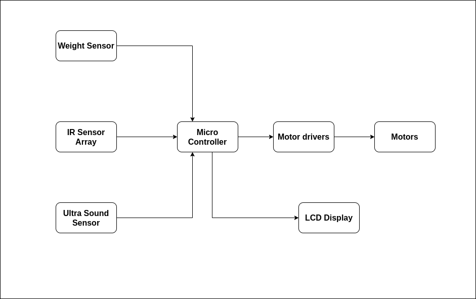
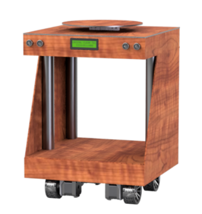
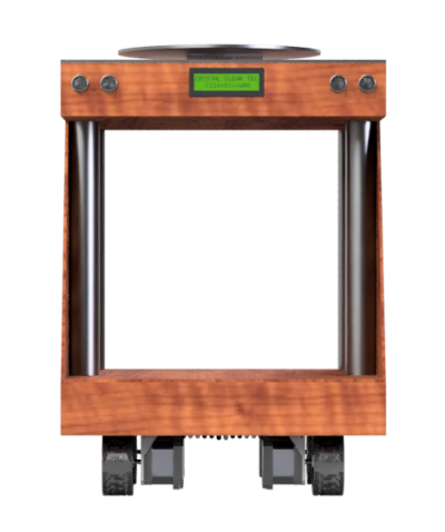
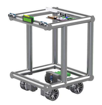
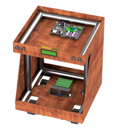
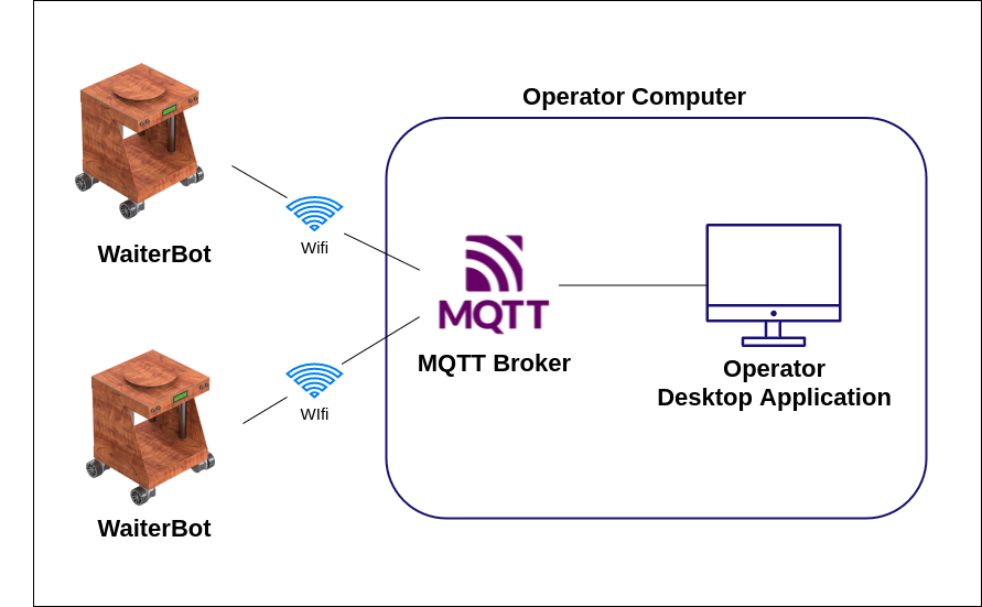
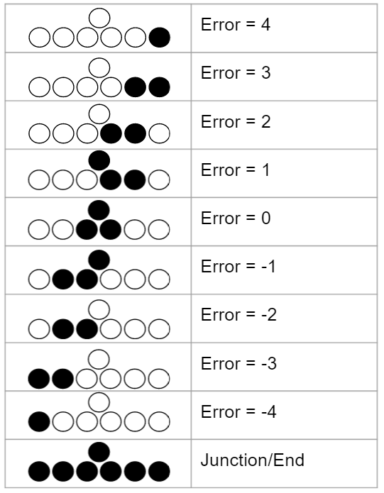
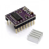
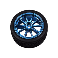
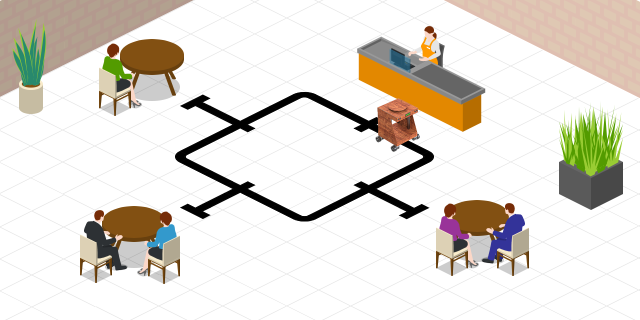
WaiterBot is the main hardware component in our system. When a WaiterBot is deployed, the control unit will send a message to the WaiterBot consisting of the number of junctions and the turning direction. WaiterBot will reach the destination table by a line following mechanism and decides the correct path to the table by keeping track of the junctions in the path.

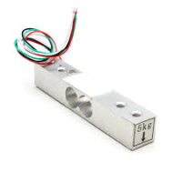
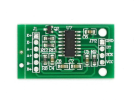
When the WaiterBot reaches the destination table, it will wait there untill the food items are taken away from its tray. Robot will ensure that all the food items are taken away from the tray by measuring the weight. When the delivery is complete the robot will return to the station and the robot can be deployed for another table.

If the robot is interfered by any obstrucle, the robot will stop its movement and inform the control unit and also if the food items on the tray are taken away from the tray before reaching the destination table, the robot will inform the control unit that the food items were taken away before reaching the destination table.

WaiterBot Features

  • WaiterBot is programmed in a way that the table layout and the path can be changed by the shop owner.
  • Alerts on interupting the delivery and on taking the items off the tray before delivery.

Communication and Protocols

Deploying of the WaiterBots are done by the desktop application. When the desktop application is launched, it will start an MQTT broker and then the WaiterBots will connect to the broker and subscribe the topic assigned for the specific robot.

Line Following Mechanism

WaiterBot will detect the path by using the readings from the IR sensor array with 7 sensors. Depending on the sensor readings, an error value will be calculated.

Using the propotionality control, the speed of the stepper motors will be controlled depending on the error vallue. That is by changing the frequency of the pulses sent to the stepper motors. To further smoothen the following of the line, PID controls will be used.

Hardware Components

ESP32

  • Quantity - 1
  • Specifications and Operating Conditions
    • Oscillator Frequency - 40MHz
    • 34 programmable GPIOs
    • SRAM - 512kB
    • Inbuilt Modules - Wifi, Bluetooth
    • Operating voltage - 3V-3.6V
    • Average current required - 80mA
  • Limitations
    • When wifi is enabled, ADC fucntion of some interfaces will not work properly. To overcome this we are using these interfaces to get digital input when wifi is enabled.
  • Why use ESP32?
    • Has an inbuilt wifi module
    • Has required ammount of GPIOs
    • Less power consumed and batteries will last long
    • High performance due to faster clock and large memory

HC-SR04

  • Quantity - 2
  • Uses the principle of reflection of sound to detect an obstracle.
  • No of sensors used - 2
  • Specifications and Operating Conditions
    • Operating voltage - 5V
    • Average current required - 15mA
    • Range - 2cm-400cm
    • Effective Angle - 15 degrees
  • Limitations
    • Distance measurement is less accurate when compared to other distance sensor modules(IR sensors)
    • Detection angle is 15 degrees. To overcome this we are using 2 sensor modules to cover the entire range.
  • Why use HCSR04?
    • We use this module to detect obstrucles and not to measure the distance to the obstrucle. Therefore accuracy not much of a concern when it comes to detecting obstrucles.
    • Dust, light and mist does not effect the reading of the sensor

IR Sensors

  • Quantity - 7
  • Uses the principle of reflection of IR light.
  • Specifications and Operating Conditions
    • Operating voltage - 5V
    • Average current required - 40mA

Load Cell - 5kg

  • Quantity - 1

HX711 module

  • Load cell outputs a voltage of micro volts. This module is used to amplify the voltage.

Stepper Motors - 17HS4401

  • No of motors used - 4
  • Specifications and Operating Conditions
    • Operating voltage - 12V
    • Rated current - 1.7A
    • Step angle - 1.2
    • Steps per rotation -200

DRV8825 Stepper Motor Driver

  • No of modules used - 4
  • Used to control the stepper motors
  • Micro contoller will send pluses and motor controller will rotate 1 step angle per pulse
  • Speed of the rotation is determined by the frequency of the pulses

Wheels

  • Diameter - 6.5cm
  • Can be coupled to the motors using hexagonal coupling

Lithium-ion Battery - 18650

  • Quantity - 6
  • Two voltage levels are required
    • 5V for the sensors and micro controller
    • 12V for the motors
  • Why lithium ion?
    • Less expensive
    • Can provide a high discharge current

Buck Converter - LM2596

asdad

Charger Protection Board - 3s 20A

  • For safely charging and discharging the battery pack

DC charger - 12.6V

  • For recharging the battery packs

LCD Display 16x02

Logic Level Converter

ESP32 operates at 3.3V and sensors operate at 5V. So when sending signals between the micro controllers and the sensors it is required to match the operating voltages. If not the devices will get damaged.

Resistors

33k and 10k resistors are required for measuring the battery percentage.