Circuits
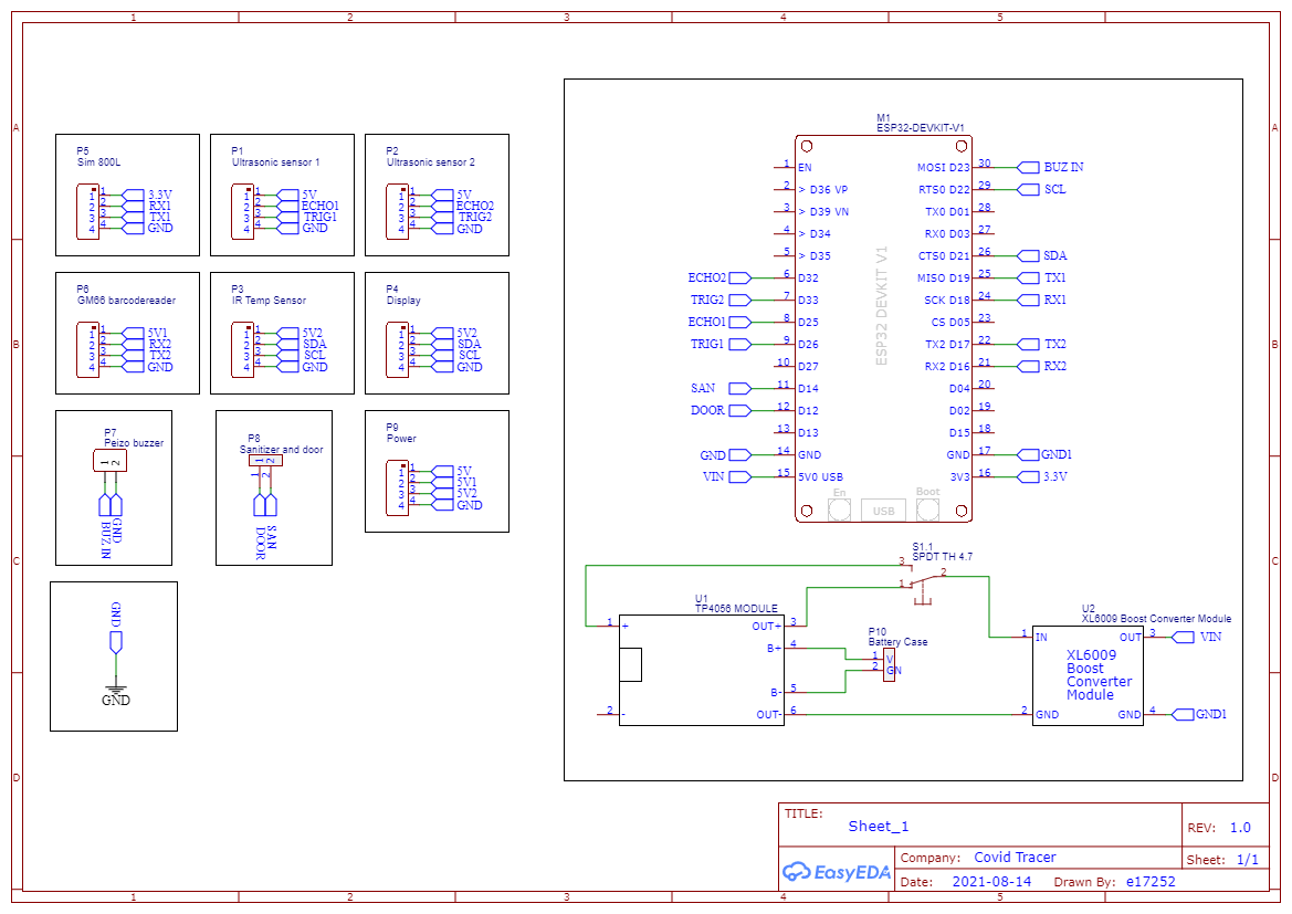
Circuit Diagram

Powr Supply Diagram

The device works with the dc power supply which is provided by an adapter from the 230V AC current. Usually the device works with the direct power from the main and it contains a Li-ion battery to supply power to the device at a power failure. This battery will be charged automatically when the device is connected with the main power. In this circuit diagram, the TP4056 Schematic_module has been used to charge the battery. Further the battery will provide a voltage 3.3V - 4.2V . Therefore it should contain a step up booster which will increase the volage drop upto 5V. That is the reason for the step up booster module(XL6009 in the circuit. To shift between direct power and battery power, it contains SPDT switch which will work to change automatically.

TP4056 Battery Charging Module

XL6009 Step up Booster Module
Schematic Design

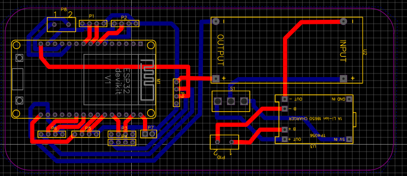
PCB Design


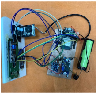
Implementation


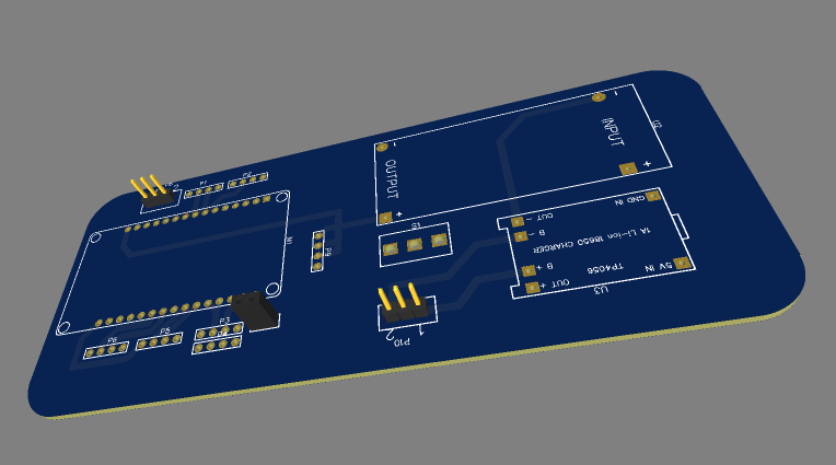
3D Print
