3rd Year Project
Department of CE - UoP
Remote Gatekeeping System
Control unit with intercom, Smart Mailbox, Mobile controlling interface,
Web services
3rd Year Project
Department of CE - UoP
The motivation to our solution
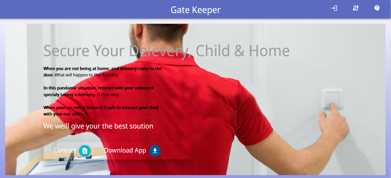
In the busy and complicated lifestyle today, keeping interactions with outsiders is, inefficient, impractical and vulnerable. The ongoing pandemic has worsen the situation becase people are afraid to having physical intractions with outsiders.
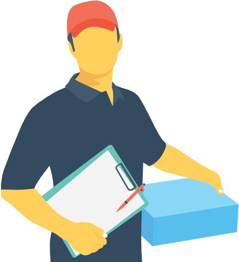
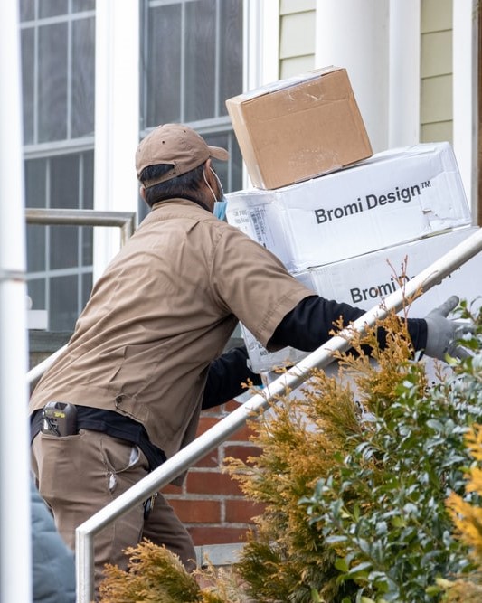
We have understood that people are having troubles with taking online deliveries to their door steps securely. Since people in Sri Lanka are so busy today, there is a good chance of not being in the house when an outsider or delivery person comes to the door.If the homeowners are not at home , delivery people are adapt to keep the delivery outside the house.Therefore delivery package is subjected to get stolen or get damaged.
Otherthan that , when an outsider comes to the door, if the parents are not home, it is not a good idea to expose the children and elder people to that outsider. It would be better if there is a way to communicate with the outsider when she/he is at the gate.(before entering to the house premise)
We thought we can come up with a system of interconnected devices (inspired from IoT) to provide an efficient solution for those problems.
How it works
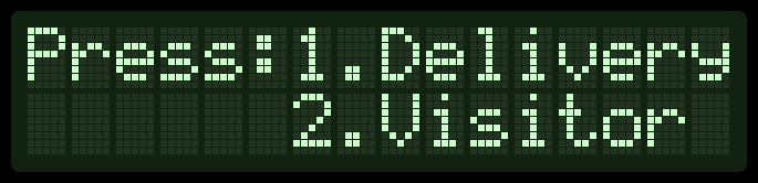
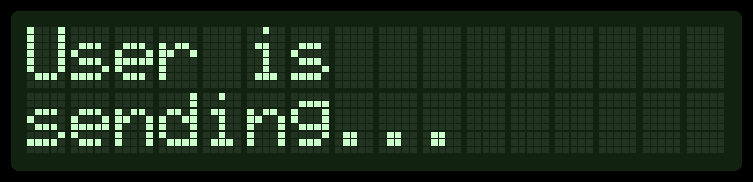
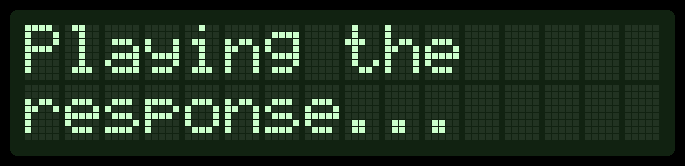
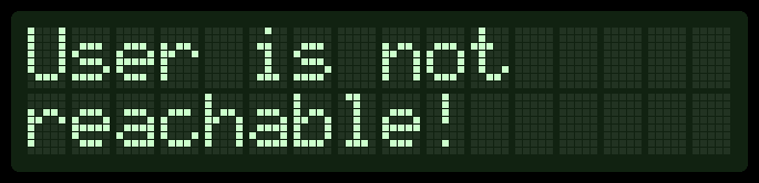
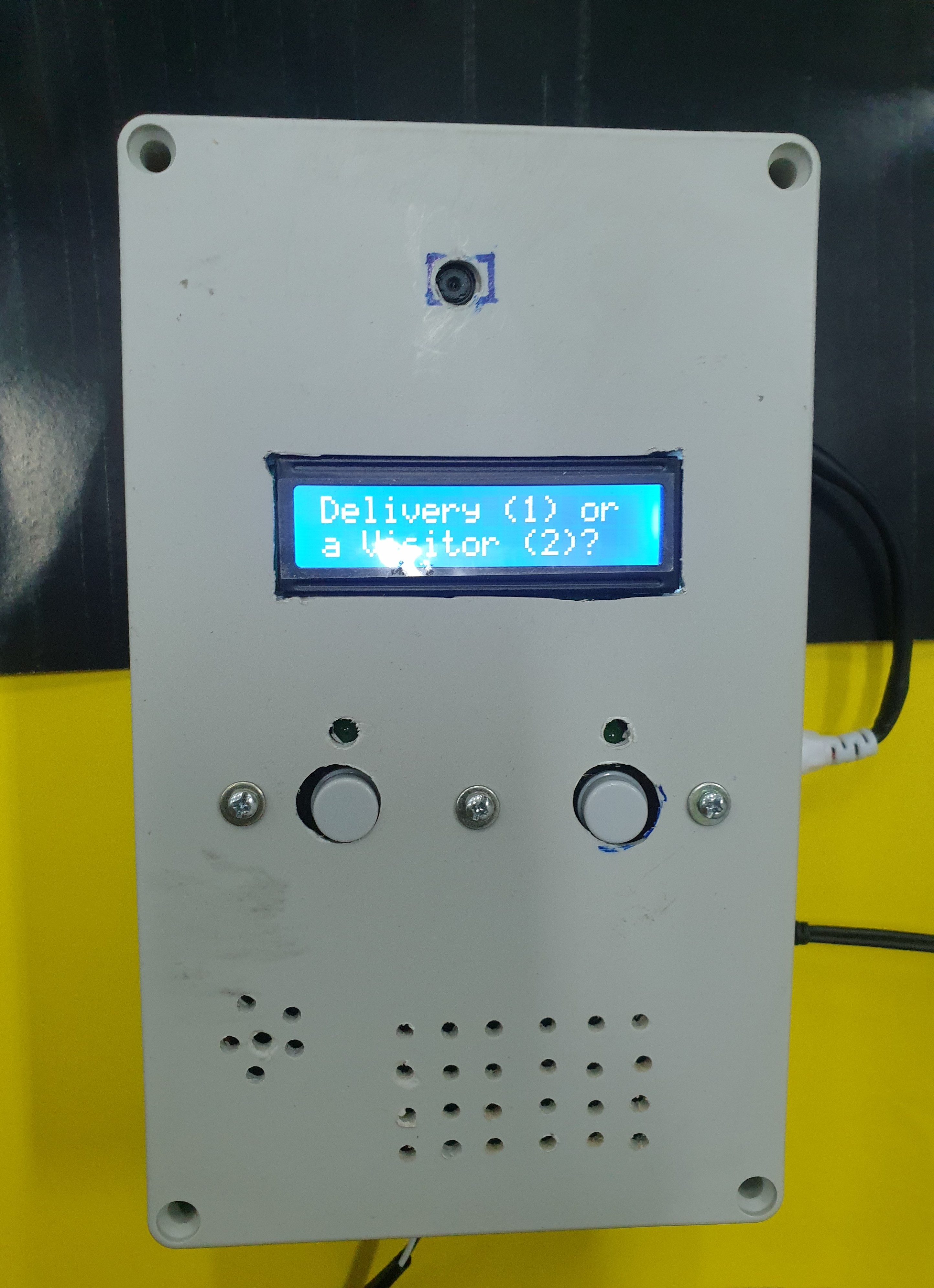
This is the main component of the system and all the cotrolling related to the system is done using this unit.Outsider interacts with this component.
This is used to receive the delivery packages safely and this can be remotely controlled by the homeowner from anywhere in the world.
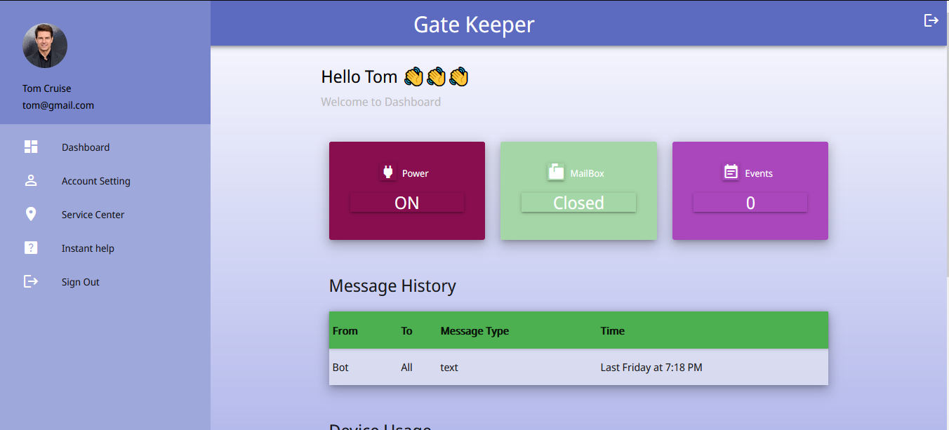
Used by the homeowner and various features like capturing the photo of the outsider, intercom with the outsider and mailbox/gate controlling is handled using this.
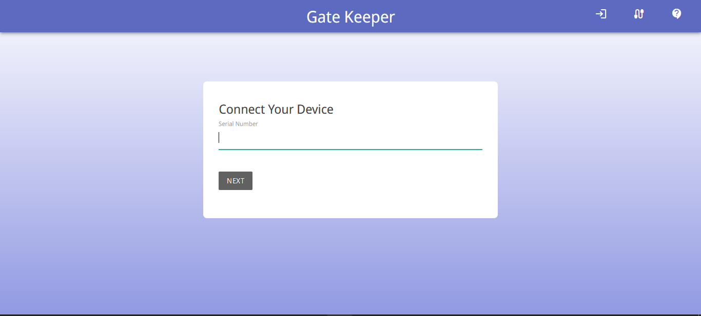
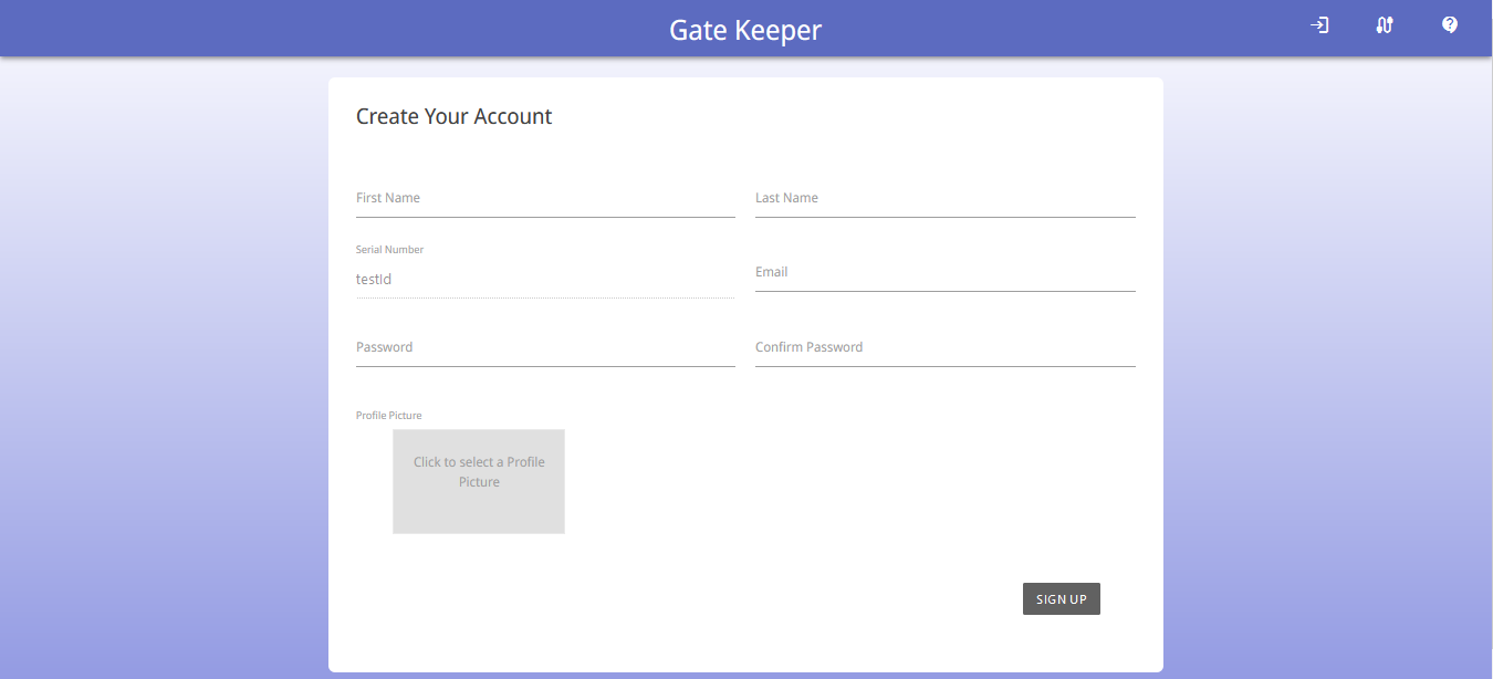
Used to sign up, establish the connection between the system with the user account , download the mobile application and various other purposes.
What happens under the hood
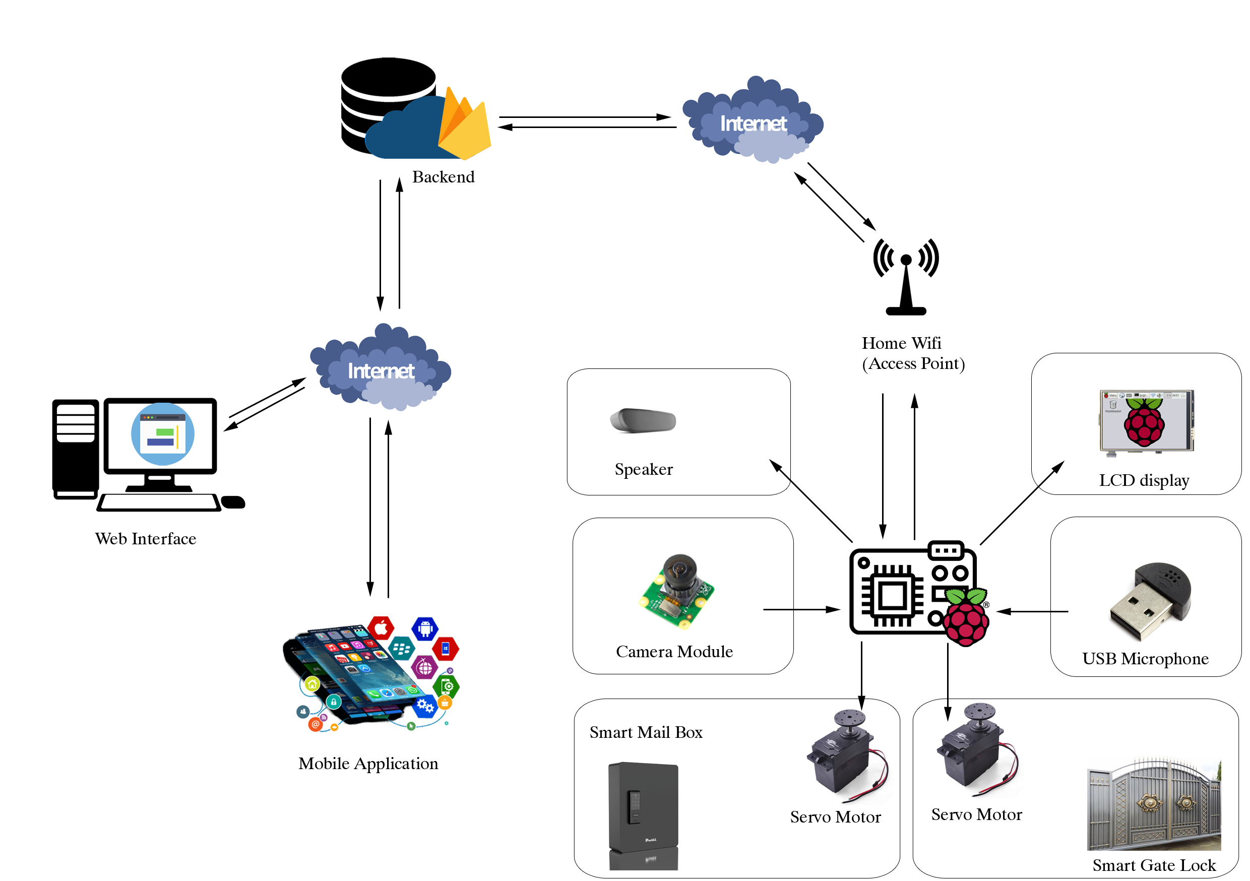
This is a high level representation of our system and it shows how our system works.
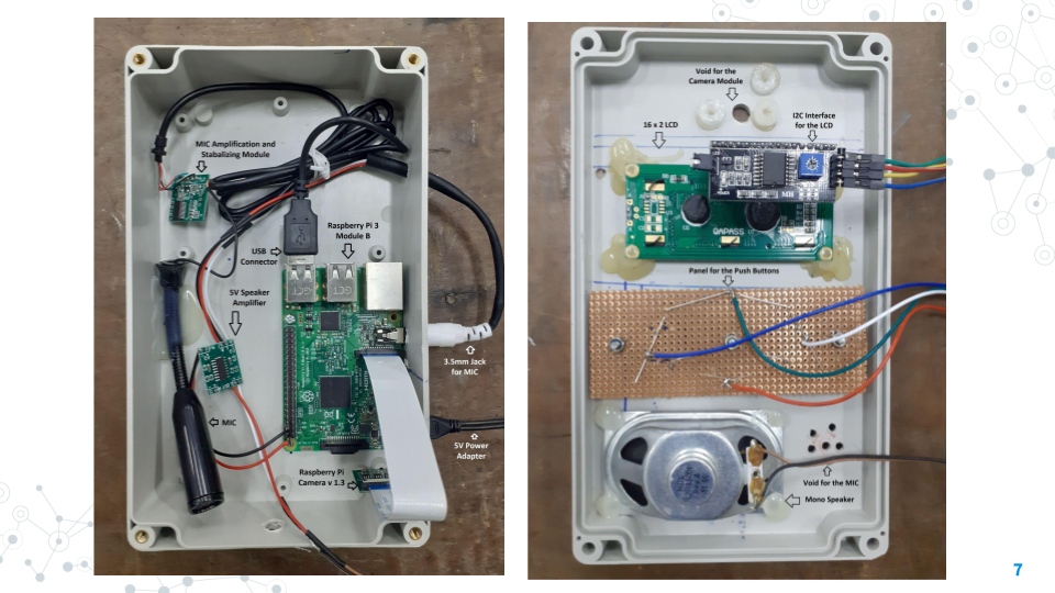
All of the modules of our system is connected to the microprocessor Raspberry Pi 3 and it will be connected to the internet using built-in wifi module through the home wifi access point.
Then it would be connected to the backend of our system which is firebase.Backend transfer data to the mobile application and the web interface. Connecting and data sharing between the hardware front-end and two software front-end is the main goal of the backend.
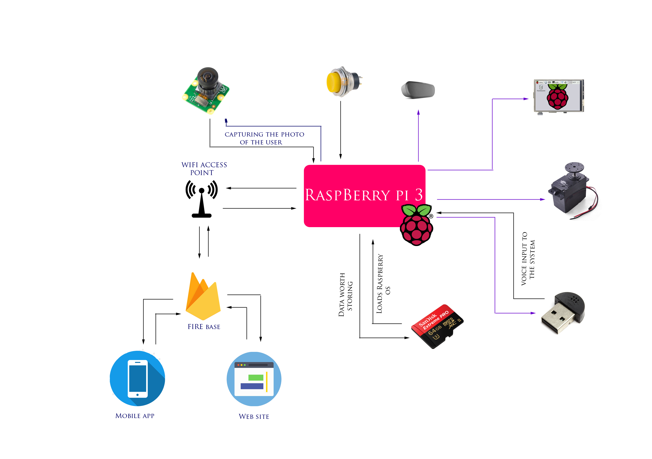
Data/Control signal distribution
This is a high level representation of our system and it shows how our the controlling and data transmission happens in the system.
Purple Lines : Control Signals
Black Lines : Data Transmission
Control signals are supplied to all the modules that are connected to the Raspberry Pi3. Data is input to the Raspberry Pi by camera module, push button, usb microphone. The SD card is used to load the raspbian OS to the system and if there are any data to be stored, they are stored using SD card.
IoT device is connected to the backend of our system therefore obvously data sharing happens there. Using the backend , the data transmission between mobile application, web site and the IoT device is achieved.
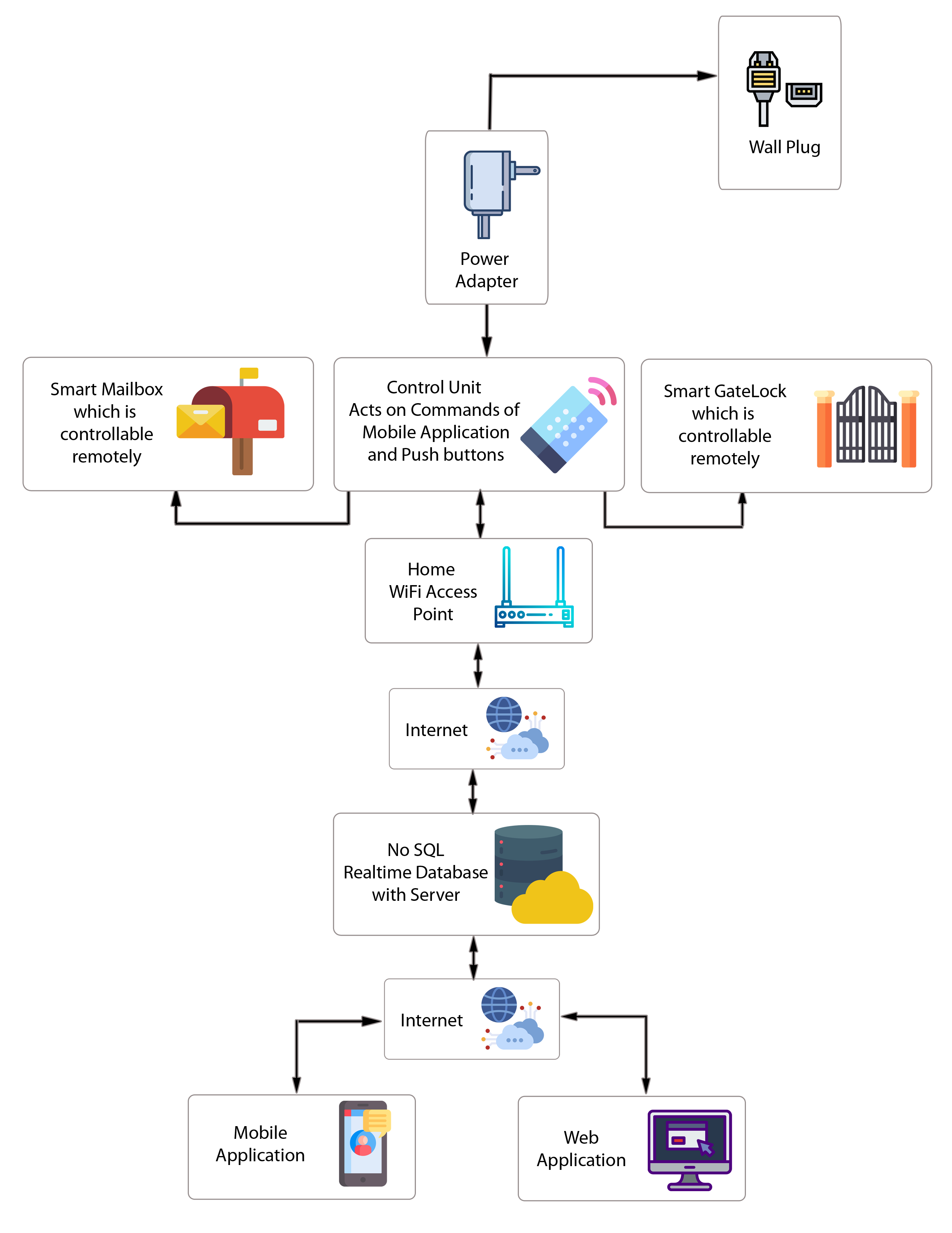
Blocks and Components
This figure shows how various components of our system interconnected.
All the controling mechanisms are handled by the control unit of our system. When the homeowner wants to open up the smart mailbox , a control signal will be send to the control unit and control unit will send a control signal to the smart mailbox and it will be opened. This exact behaviour is applied for the smart gatelock as well.
The control unit is going to connected to the power supply adapter and will get power from the wall plug. Then the power required for smart mailbox and smart gatelock will be provided by the control unit itself.
Then it would be connected to the backend of our system which is firebase.Backend transfer data to the mobile application and the web interface. Connecting and data sharing between the hardware front-end and two software front-end is the main goal of the backend.
UX-UI Design
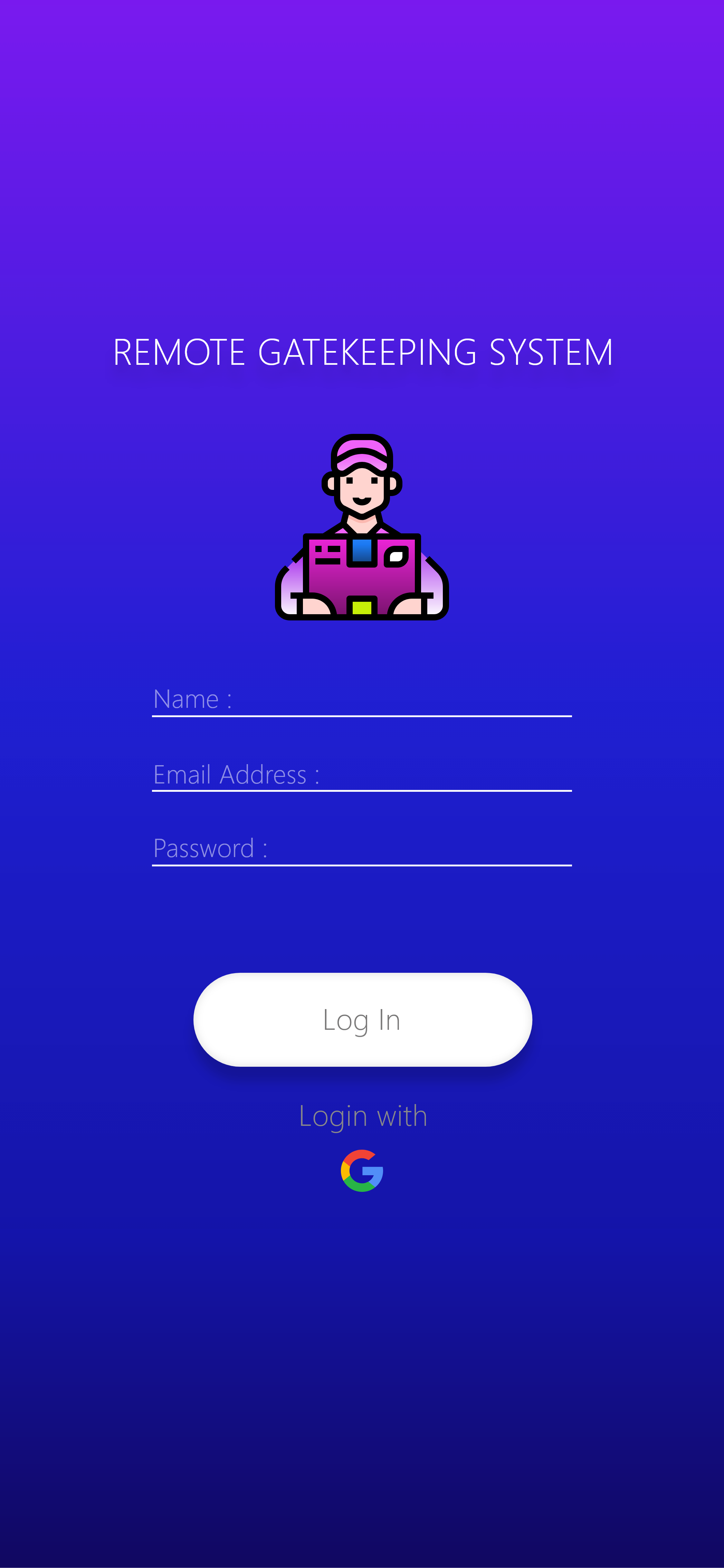
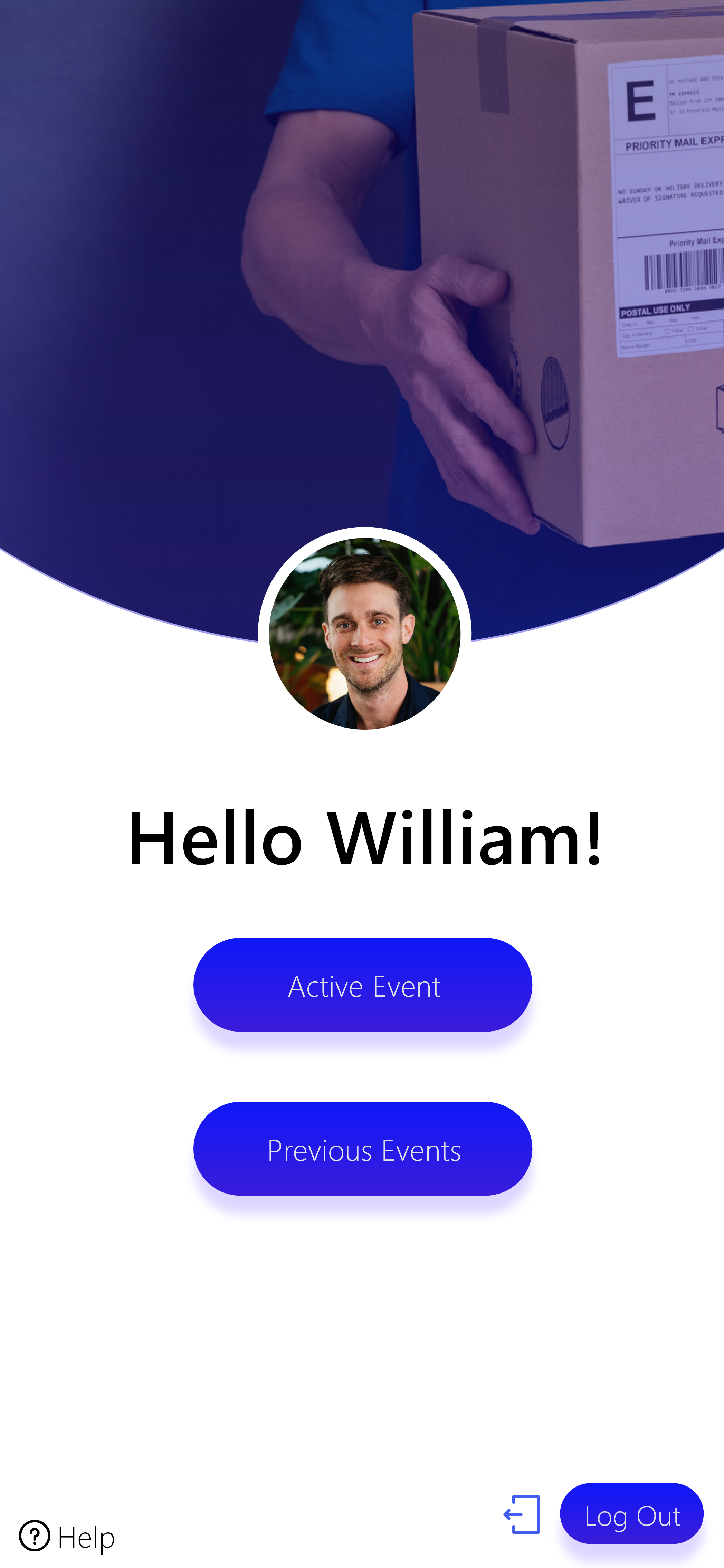
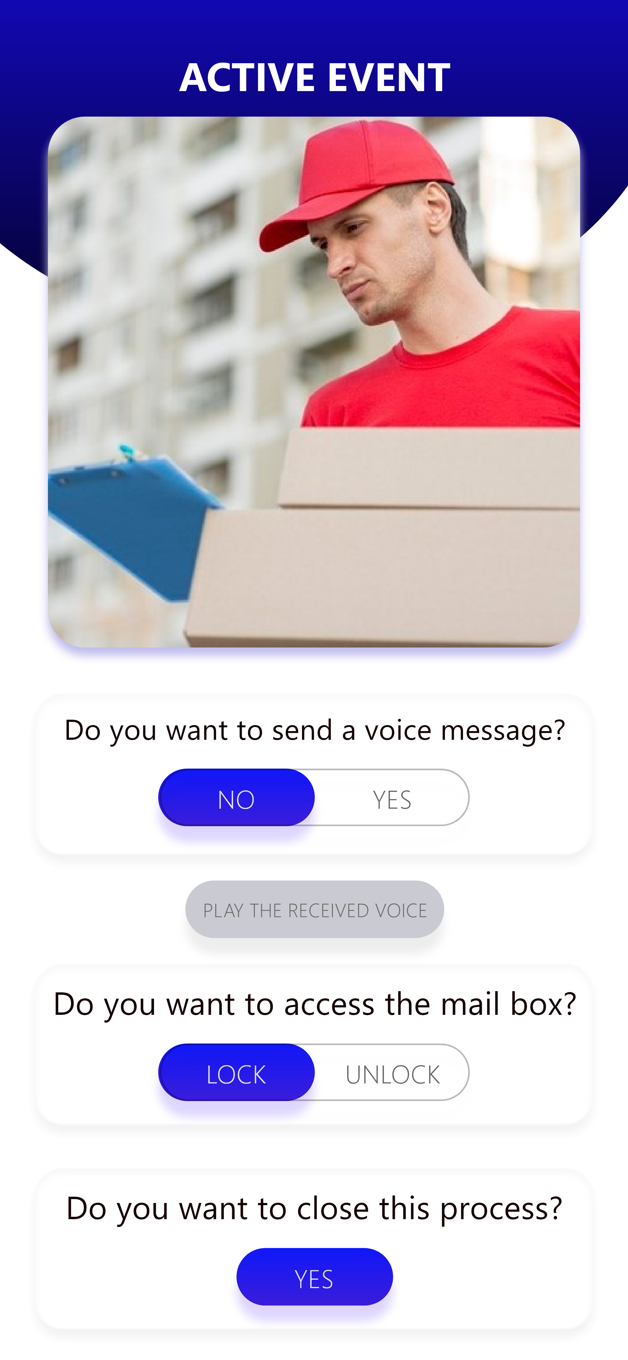
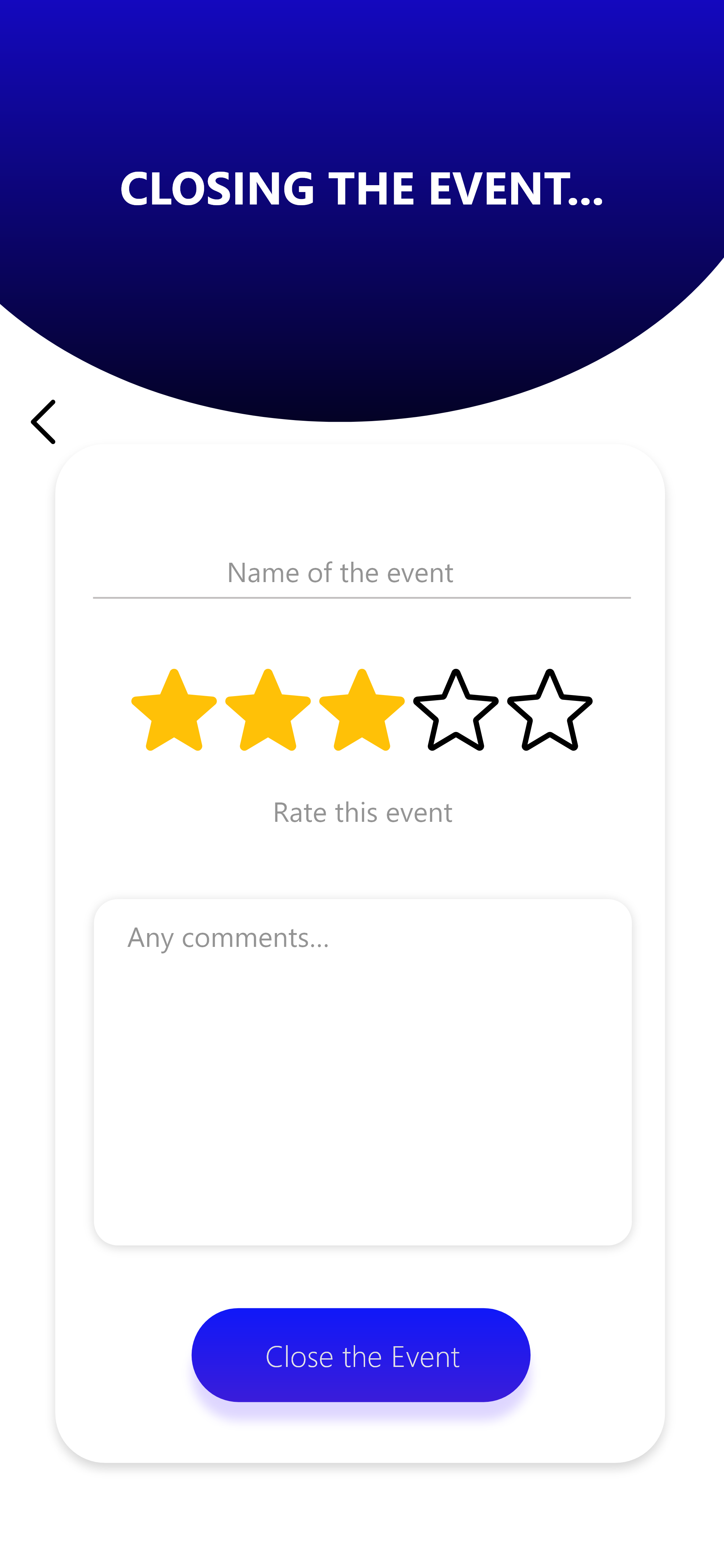
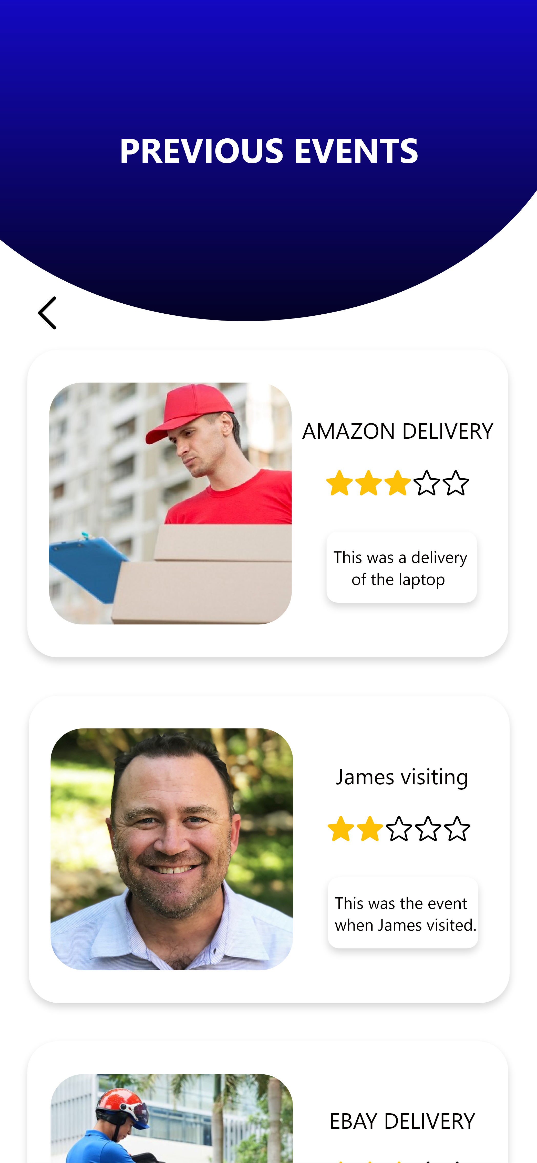
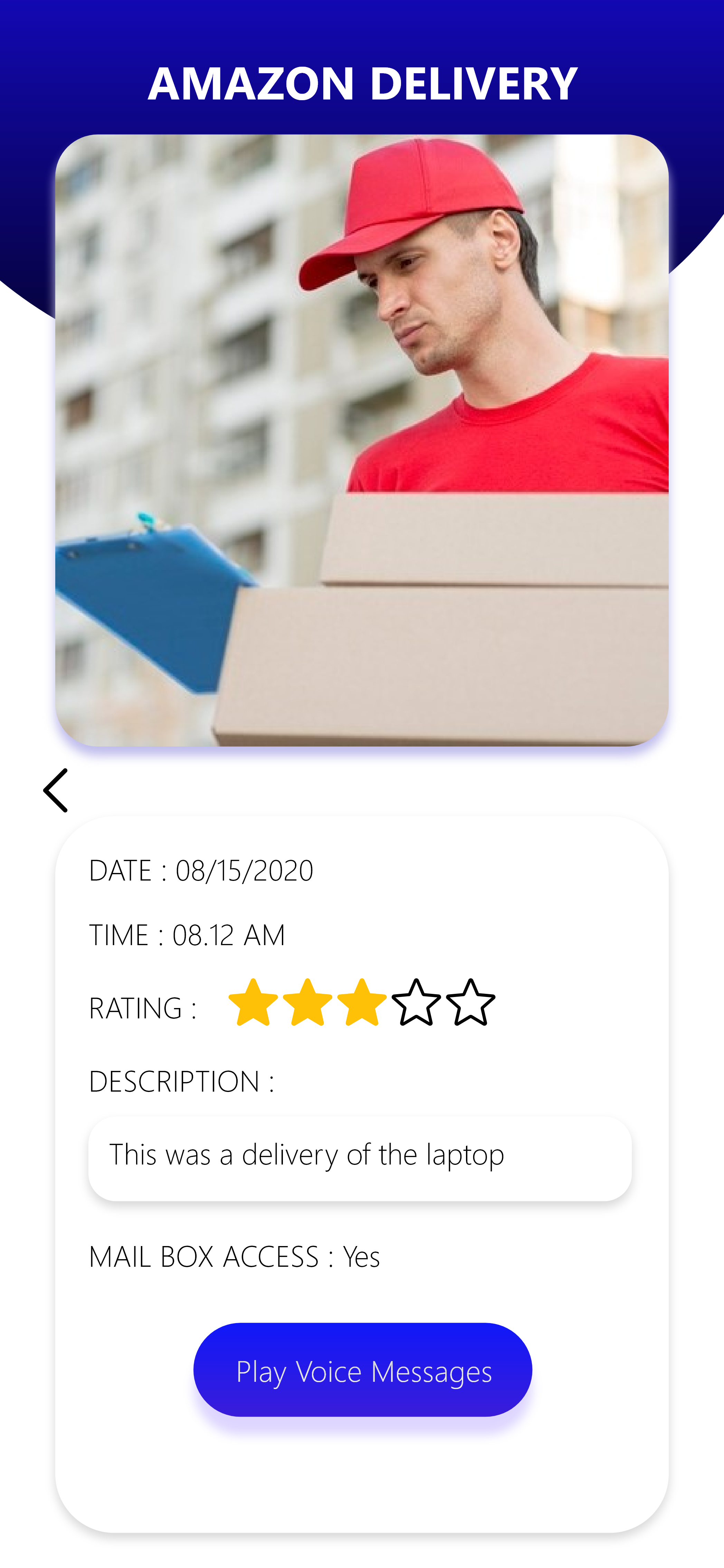
UX-UI Design
UX-UI Design


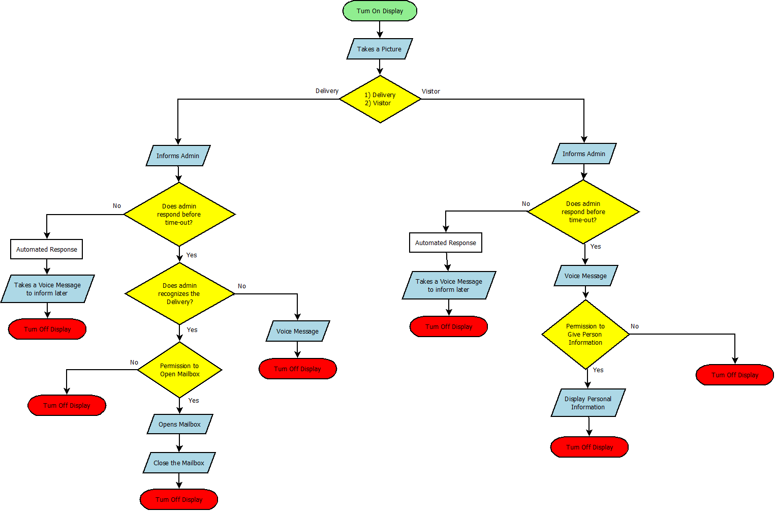
Algorithm runs on the hardware module
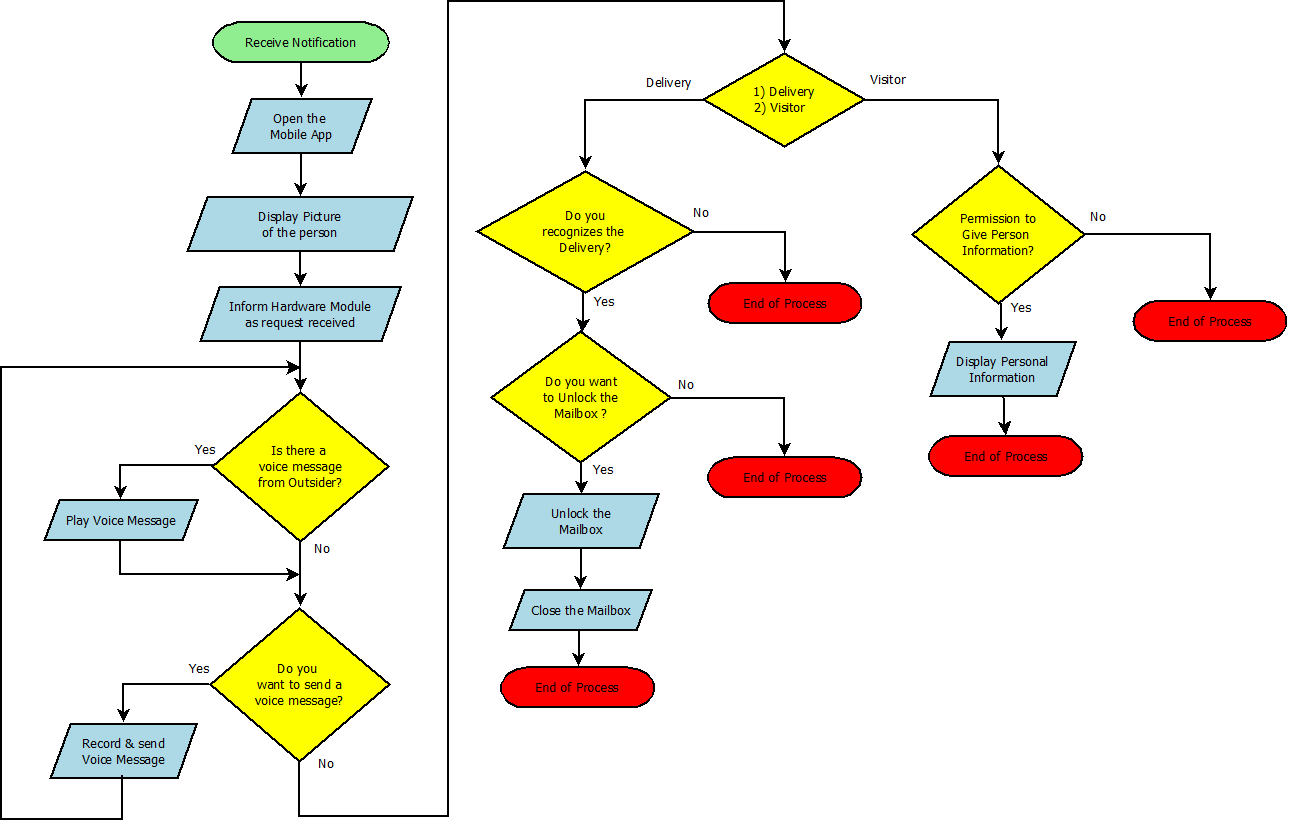
Algorithm runs on the Mobile Application
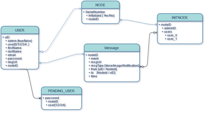
how we store the data
We use Firebase Realtime Database as database of our system which is a cloud-hosted database. Data is stored as JSON and synchronized in realtime to every connected client. That means all the clients connected to our system share one Realtime Database instance and automatically receive updates with the newest data.
Firebase Realtime Database is a non sql, dynamic and non relational database.
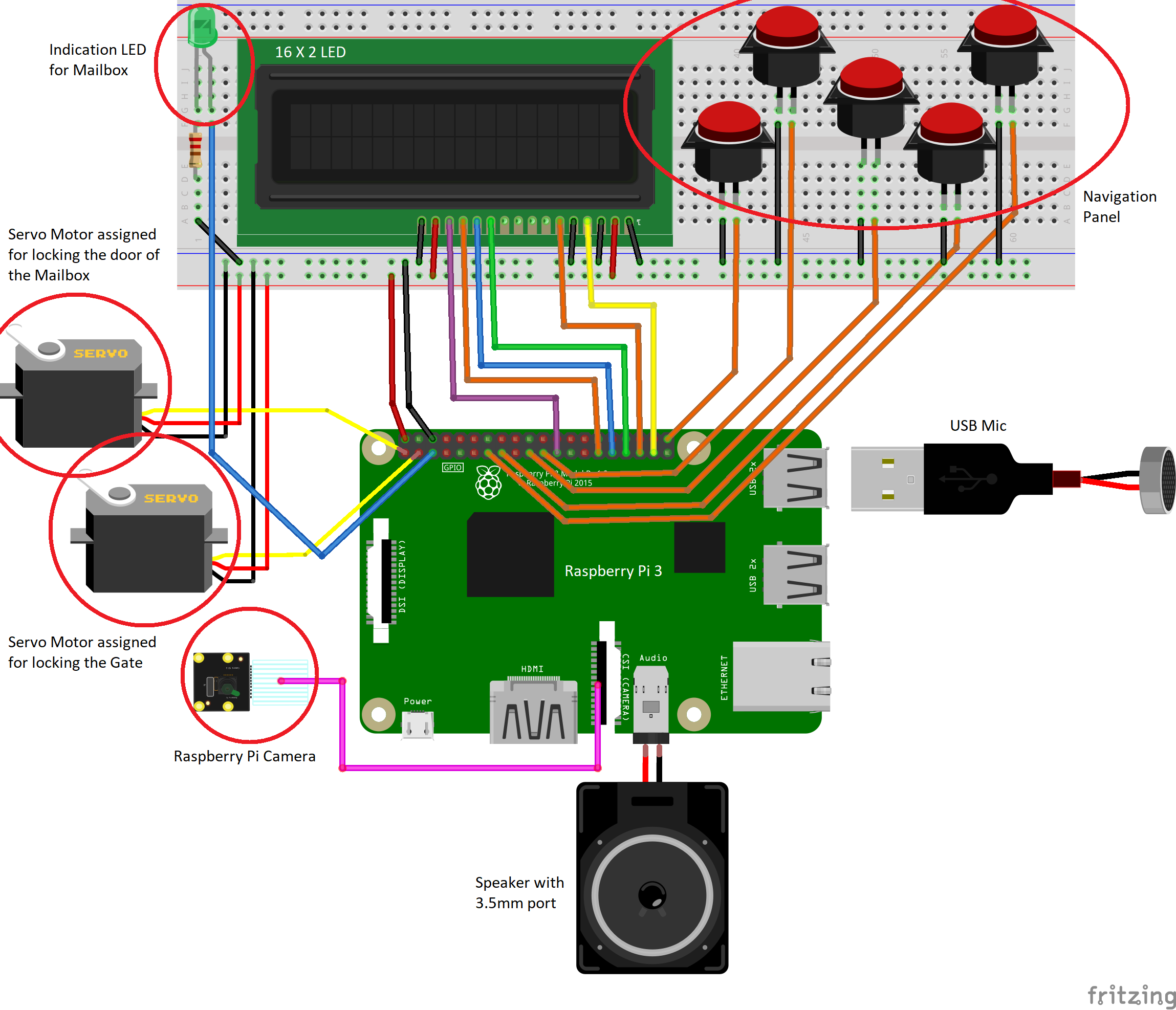
How the modules are connected
What we have implemented so far...
hardware modules
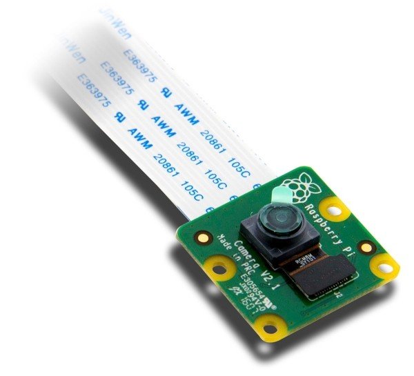
8 Megapixels
Several image formats (JPEG, BMP, PNG) - smaller file size for faster and effective transmission
300mA current, 1.2V
RPi library: PiCamera
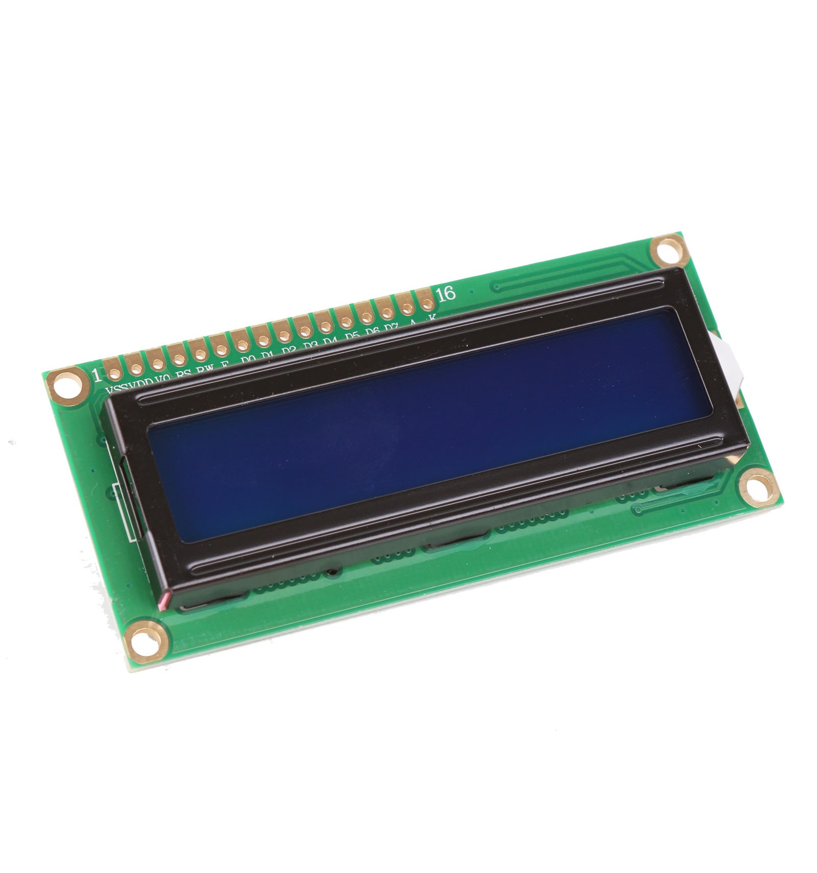
Affordable
Suits our requirements
Consumes less power compared to other options (3.3 ~ 5V)
RPi library: Adafruit_CharLCD
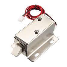
Mechanical locks of the Mailbox
Solenoid lock denotes a latch for electrical locking and unlocking
Consumes around 12V
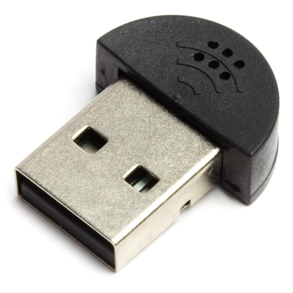
Very reliable for voice recording, which allows optimum communication in Intercom
Works great with a Raspberry Pi computer
5V of electricity with a maximum current of 0.5A
Factory Calibrated
From Week 1 to Week 15
bakcend services
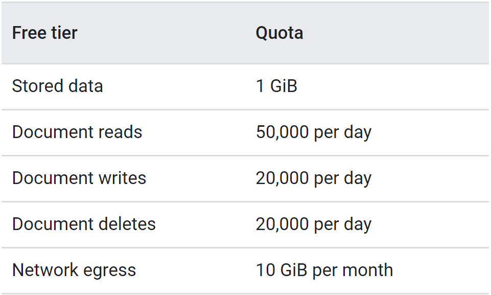
For now, we are using the free tier of the Firestore. Cloud Firestore offers free quota that allows you to get started at no cost. The free quota amounts are listed here.
Firebase offers upto 50,000 document writes per day. We have observed about 25 database reads will take for a single event. If we assume a normal user may encounter 10 events per day, we can handle about 200 nodes per day in the free tier.
Firebase Realtime Database provides 100 simultaneous connections for the free tier. Since we are not expecting that much of events at the same time, it won't be a bottleneck. If it was, we can easily boost it to 200k by upgrading the system to paid tier.
Firebase Realtime Database offers upto 5GB of data storage per day for the free tier. We have analysed for several test cases and found out average event may contains files upto 3MB. Since we are hoping to provide 1 month of backup data, it will be enough for 5 nodes. We can reduce the backup size to accommodate more users, or we can switch to paid tier. Additional 40GBs costs $1 and for that we can provide backup for 40 users.
As a future Implementation, we are going to scale the system to have the ability of connecting several users for a single hardware node.
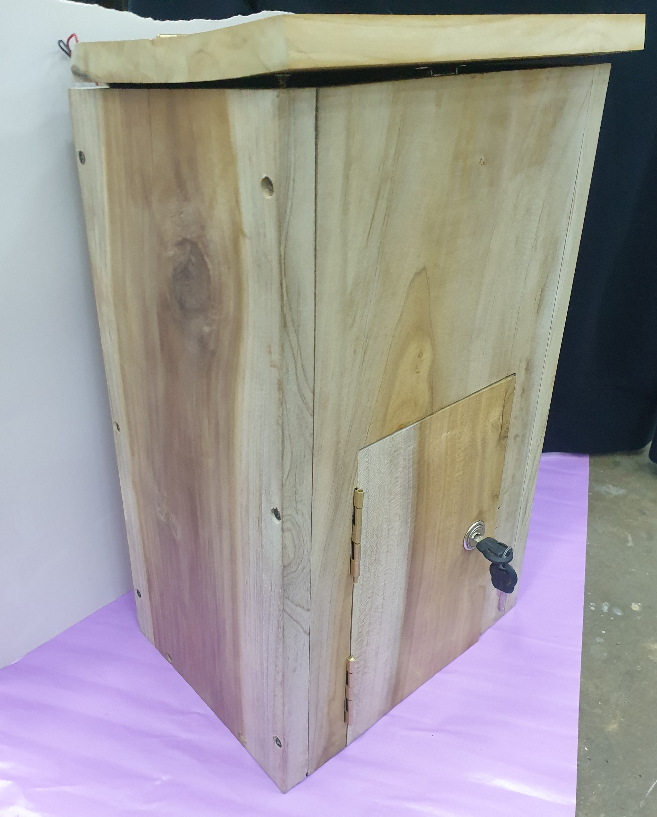
Physical designs of our system
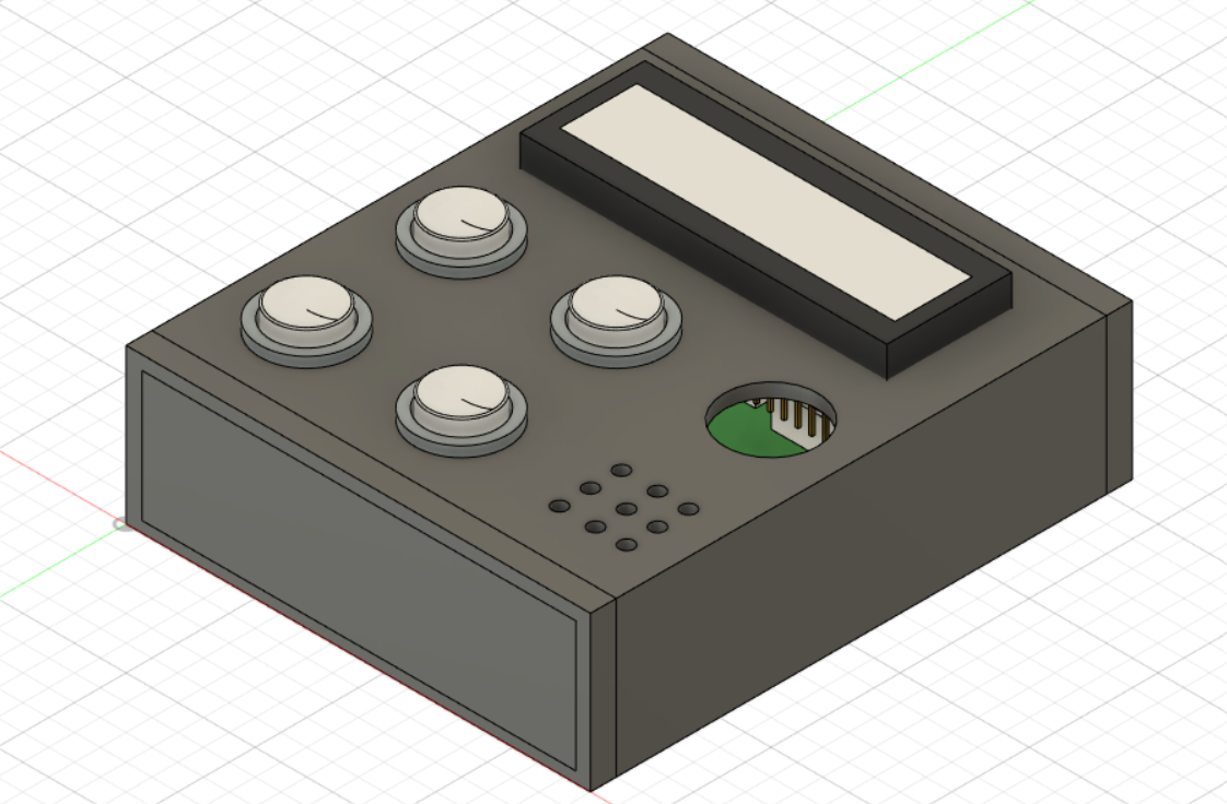
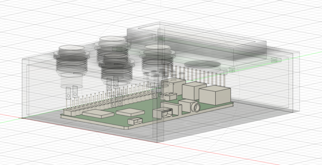
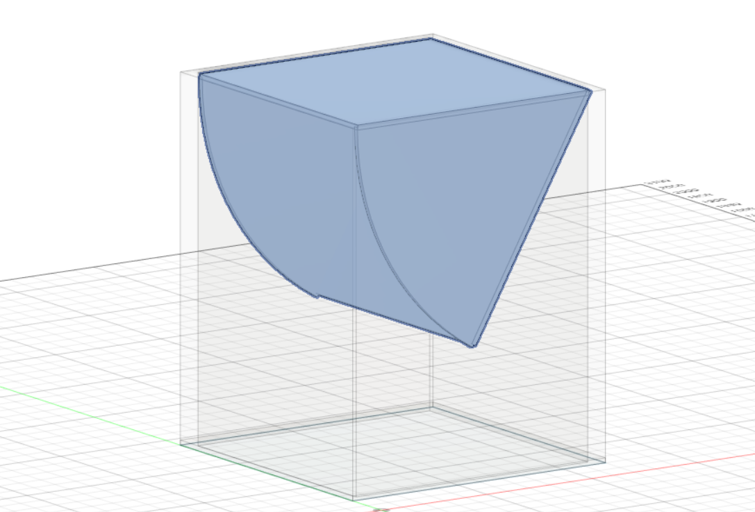
Packagings of our system
Group 19