The Smart Locker is a improvement for the traditional locker where we are trying to provide the lockers for public usage. Normal traditional lockers were used privately but as a team we think if lockers can be provided in a public way where citizens will book lockers for their access in public places it would be a market opportunity. We are as a team will develop a locker with digital improvements where users can unlock the locker by purchasing it online for a certain time period. The Lock itself will be developed by a arduino based electronic system where set of lockers will be monitered by a centeralized system.
People from remote areas travel a long distance to the town in their day-to-day life. Employees come for their jobs. Students come for educational purposes such as schools and tuition classes. All these times they carry a lot of things here and there because they have to carry everything that they need in one go. So as a team we understand it is very difficult for those people. Then we came up with the idea of public lockers for making their day-to-day life easy. As a result we also understand that there are many people who can benefit from our solution rather than people who live in remote areas. This led to finalizing our idea as well.
⚫ Operable by a phone’s mobile application
⚫ With map assistant to find where the lockers are
⚫ Users can book lockers using application for certain duration of time.
⚫ When booking users will receive a token.
⚫ User can either use their phone or enter the token number to unlock the locker
⚫ Token can share with another trusted person for accessing the locker by himself.
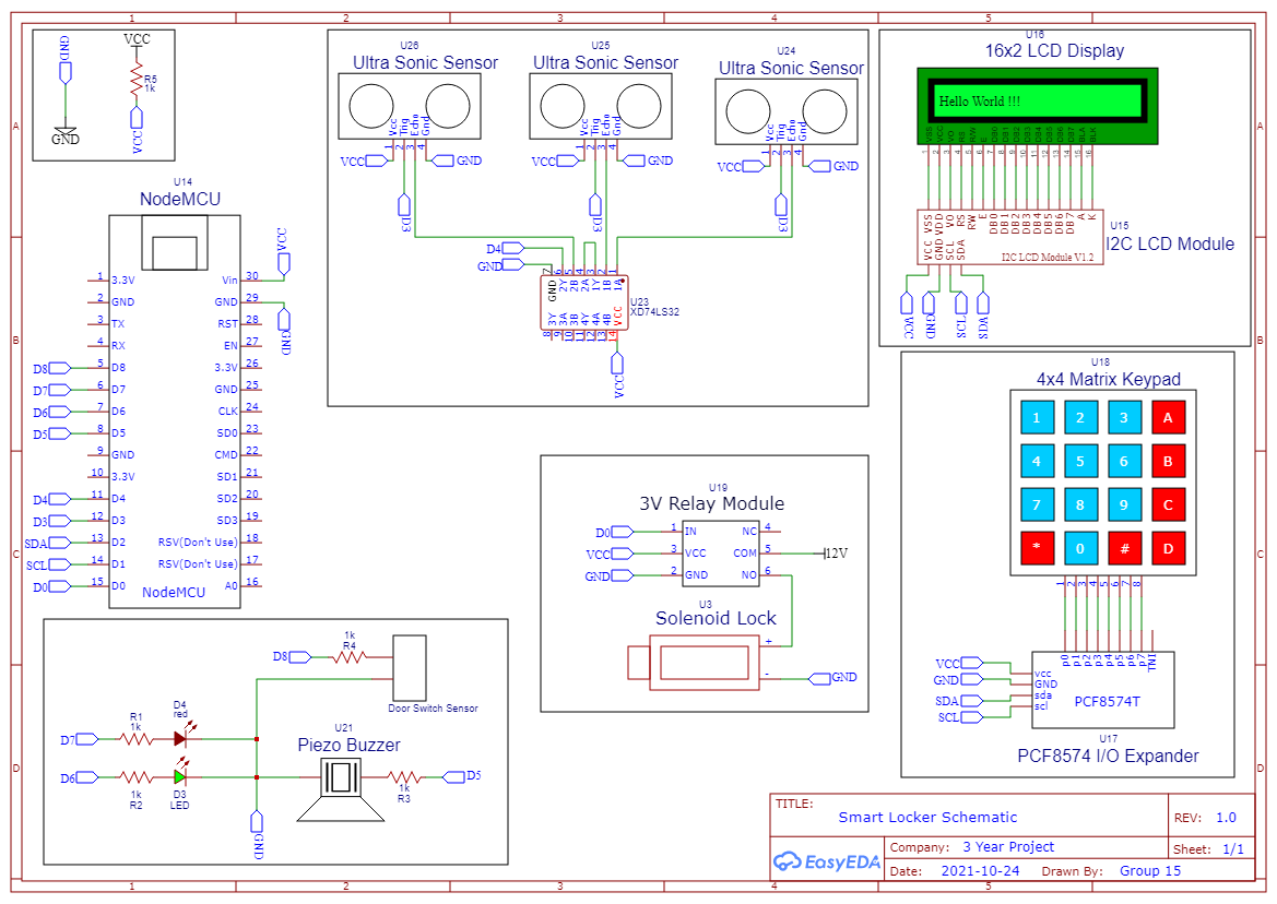
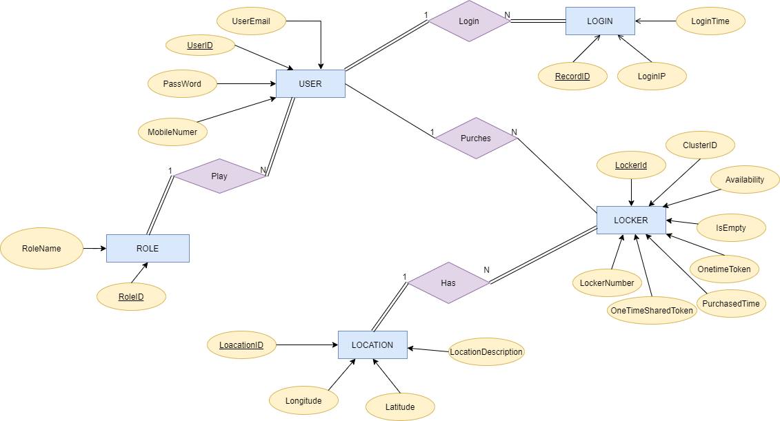
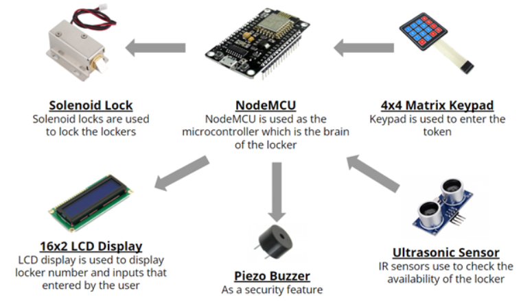
This system consists of three main segments. The first one is the Locker. Others are backend and frontend which is also known as the mobile application. Smart locker includes four main parts. There are two input devices and they are Keypad and Ultrasonic sensor. There are two output devices and they are LCD display and solenoid lock. The keypad is used to enter tokens and other data. The Ultrasonic Sensor, helps the user to detect locker is empty or not. Through LCD display user can observe messages from the locker and the token which is entred. Initially, general information of lockers is stored in the cloud server database and it provides data to the mobile application and lockers. Also, it collects user data through the mobile application and the Locker. Users can ask about lockers and it gives details such as availability etc. If the user books a locker, then the backend generates a new token and sends it to the locker and user. The main functionalities of the locker are handled by the microcontroller and it makes a connection to the server through a Wi-Fi network. In advance, as a security feature buzzer is used. Finally, to enhance user experiance two LEDs are used for correctly identify whether the lock is in locked mode or not.


⚫ Prevent unauthorized access from the mobile application
⚫ Block user IPs using a rate limiter
⚫ Validate user inputs
⚫ JSON Web Tokens for authorization
⚫ JWT signature validation
⚫ Encrypt the user password in the database
⚫ Update locker password after every single usage
⚫ Record login details
⚫ Block unwanted traffic using built-in AWS firewalls
⚫ Durable Solenoid locks and lockers
⚫ Sound buzzer if something wrong went wrong or malicious thing happen
⚫ Private wi-fi connection for each cluster of lockers
⚫ Solenoid lock is in Locked state at a power failure
⚫ Solenoid lock is in Locked state at a server failure
⚫ Show warnings to users
⚫ Data fetched from sensors are stored within the device for a certaion period
⚫ Send that data again to the server to mitigate if lost updates happen
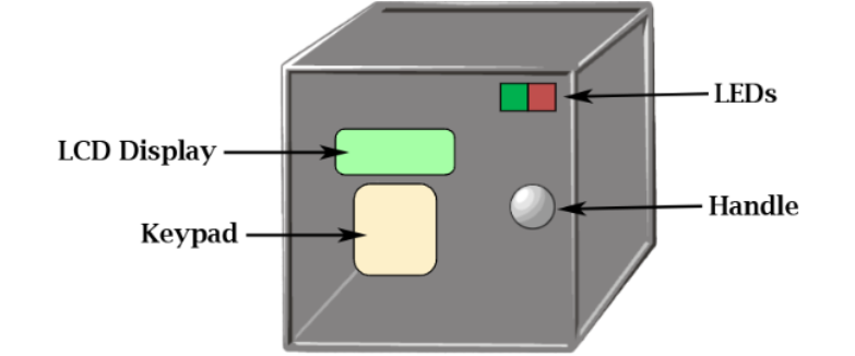
The physical implementation of the hardware will look as above, where it consists of the LCD Display, Keypad, Handle and the LEDs. Keypad is used to input the passwords, LCD Display is used to display necessary information like the password and free nature of the locker, Group number and locker number. LEDs display whether the locker door is open or not.
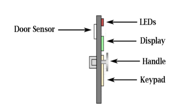
The Lateral view of the hardware shows two additional components the Door Sensor and the Solenoid lock, the solenoid lock is used to lock the locker and open the locker whenever necessary. The Door Sensor is used to check whether the door is open or not and change the color of the LEDs that are connected to the door.
The inner cross section of the locker shows what is there inside the locker, there are Ultra Sonic Sensors to identify whether there is an object in there or not. Other than that, there is the component box where it includes the microcontroller and the wirings that are required to make the connections between the hardware components.
1.NodeMCU
Used as the main micro controller and the processing unit of the hardware system.
And a ESP8266 IC is integrated into this Micro controller.
This can be used to connect to internet using Wi-Fi when programmed to do so.
Power Supply is provided to the Node MCU Using a 5-volt 2-ampere power regulator (power pack).
The positive terminal is connected to the Vin pin of the Micro controller while the ground of the power pack is connected to a ground pin of the NodeMCU.
The D1, D2 pins are connected to SDL and SCL of the I2C expander.
These pins are predetermined by the NodeMCU and the SCL of the expander is always connected to the D1 pin of the NodeMCU.
and SDL pin is always connected to the D2 pin of the NodeMCU.
A0 is connected to the door sensor.
When the door is opened there will be an analog signal which will send into the NodeMCU.
That signal is processed by the NodeMCU and two LEDs (Green and Red) which are connected to the D3, D4 pins of the NodeMCU will be lighted accordingly.
D5, D6 Echo and Trigger pins of the Ultra Sonic Sensor the D5 pin is connected to the Trig of the Ultrasonic Sensor
while D6 is connected to Echo Pin of the Ultrasonic Sensor.
D7 is connected to the 5v 1channel relay in pin.
The negative logic will switch the relay into normally open port of the relay.
2. 5V 1Channel relay
The D7 pin in the NodeMCU is connected to the “IN” pin of the relay.
The power is given by 3.3v pin on the NodeMCU while ground is connected to a ground pin or ground of the 5v input that is given to the system.
The 12v power supply of the power pack is connected to the common of the relay
and the positive terminal of the solenoid lock is connected to the normally closed terminal of the relay.
The solenoid lock is connected to the normally closed terminal because then in most of the time the lock is closed by current is running through it therefore it will not get heated up.
3. Solenoid Lock
The solenoid lock is used to open and close the locker.
When a current is not provided it in the closed condition therefore the locker is locked.
When we provide a current to the solenoid lock it will open up therefore the locker is also opened.
The locker is connected to the normally closed terminal of the relay.
Therefore, when a signal is received via “mqqt” the d7 pin will send a signal therefore the locker will open up.
A 12v power pack is used to power up the solenoid lock.
therefore the positive terminal of the 12v is connected to the common of the relay
while the negative terminal of the solenoid is connected to the negative of the power pack.
4. 4x4 Matrix keypad
The keypad is used to input the passwords into the locker,
the inserted password is displayed on the display.
The power supply to the keyboard is provided via the I/O expander.
The power for the I/O expander is given through the 5v power pack.
5. 16x2 LCD Display
The LCD Display displays the required information of the locker.
It will show the group number and the locker number and the availability of the locker,
once someone rents out the locker then the availability is set to zero.
When someone is inserting the password,
it is displayed on the display and if the password is correct,
it will display “the password is correct” and if not, it will display the “password is incorrect”.
The power is provided to the display via the expander, and it takes 5v.
6. Ultrasonic Sensor
The Ultrasonic sensor will detect whether there is an object or not within the locker and it will send that value to the micro controller.
By using this signal the customer will surely know that there is an object inside the locker.
The power for the ultrasonic sensor is taken from the 5v input that was given in by the power pack.
We are implementing two lockers as a bunch with the functionalities described above. Then an item is put in one locker. So it is unavailable. One of our team members books the available locker using the mobile application with map assistance. Then he opens it through the mobile app and puts something in it. Afterwards, he shares the token that he received with another team member. This other guy opens the same locker using the mobile application as well as the keypad by entering the token. Moreover, after expiring the time duration, the owner cannot open the locker furthermore.