

Features of our smart devices
Smart-bulbs
Smart Switches
System
Introduction
Smart-Home is meant for convinence and efficecy. Controlling and monitoring your home by your smart-phone make things easier. Smart-bulbs,smart-switches and smart-bliends make your home more smarter.
Problem
In the Non-smart-Homes or the traditional homes, so much energy waste is due to improper management. Monitoring the full home appliances is insane. When the peak of the electric bill, we don't know what eats the power so much. It is so inconvenient some time for example, when you forgot to turn off the light before sleeping or going far away and forgot to turn off your bulbs or switches..
Solution
Solution is simple. Using concepts like IOT, HCI and AI(future plan) we can implement smart devices for the homes. They can be control using our mobiles and they can semi-automated. And also you can monitor your home power consumption details by using and smart-switch embeded with voltage and current sensor. For this project we going build smart bulbs and the switches.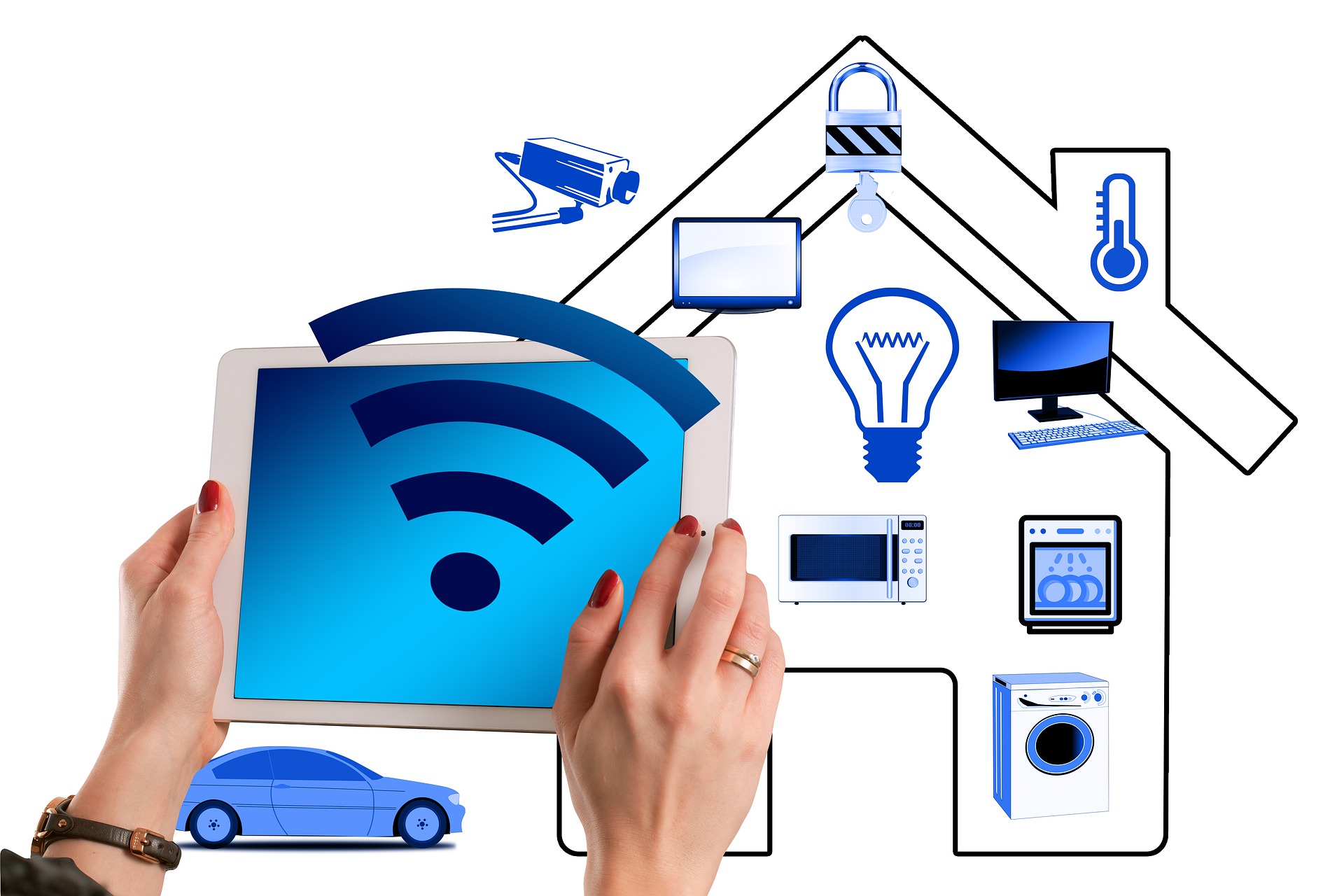
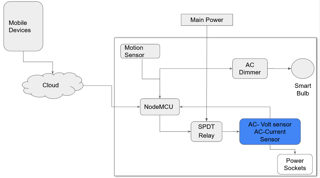
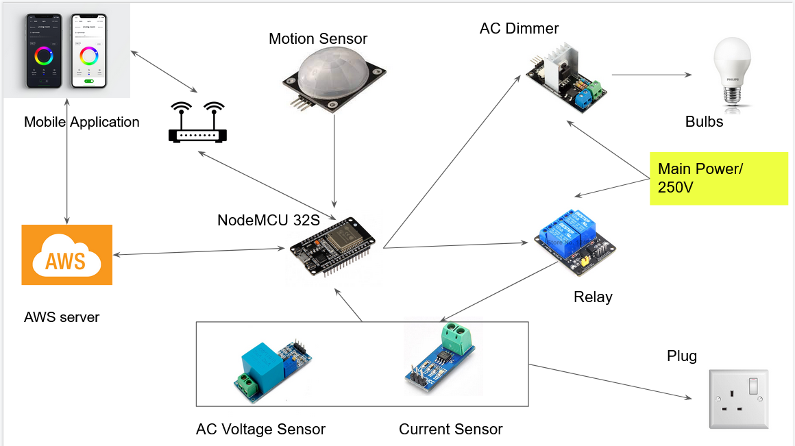
Solution Architecture
Our solution Architecture contains two types of devices, they are
Smart-Bulbs & the Smart-Switchs. They both devices, sensors like motion
sensor,
AC current sensor, AC voltage sensor and the Rellay are directly connected with the Central
Unit.
Our mobile application and the central unit connectedto the cloud via internet. So they can
communicate
with them-self. The central unit will use the MQTT protocol to communicate with the
server.
The energy consumption monitoring, this is a feature embeded with all the switches to
calculate the
energy consumption and update it to the cloud. This is can be implemented using Two sensor
AC Current
sensor
and AC voltage sensor.
Motion Sensing, Motion sensing is another feature built-in with the bulbs, The motion
sensors are
connected
to the central unit. When a motion detected or the central unit wil turn on the bulb and if
no
motion/human detected
the CU will turn off the bulb.
Mobile applications communicate with the central unit through the cloud or diretly using
wifi router.
The User settings, user data, and the reports will be stored in the cloud/server.
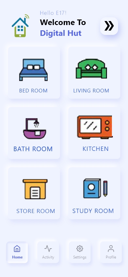
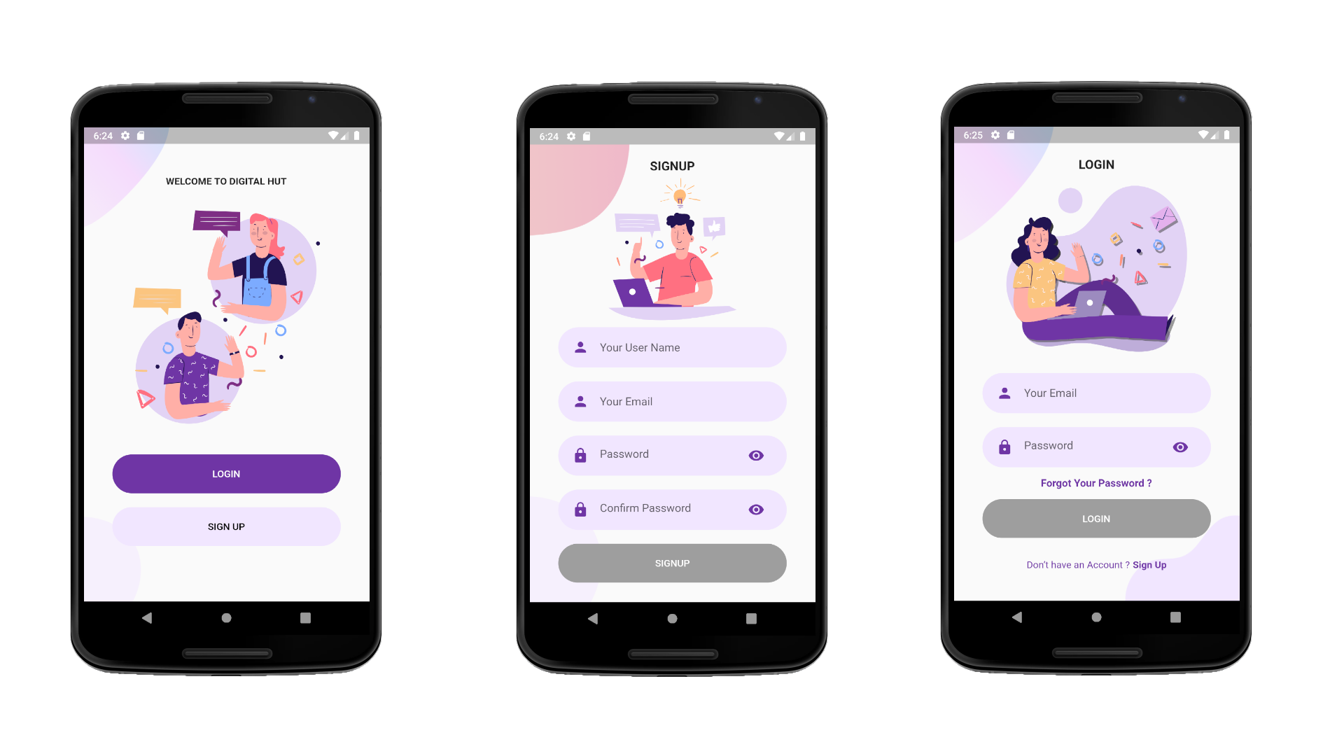
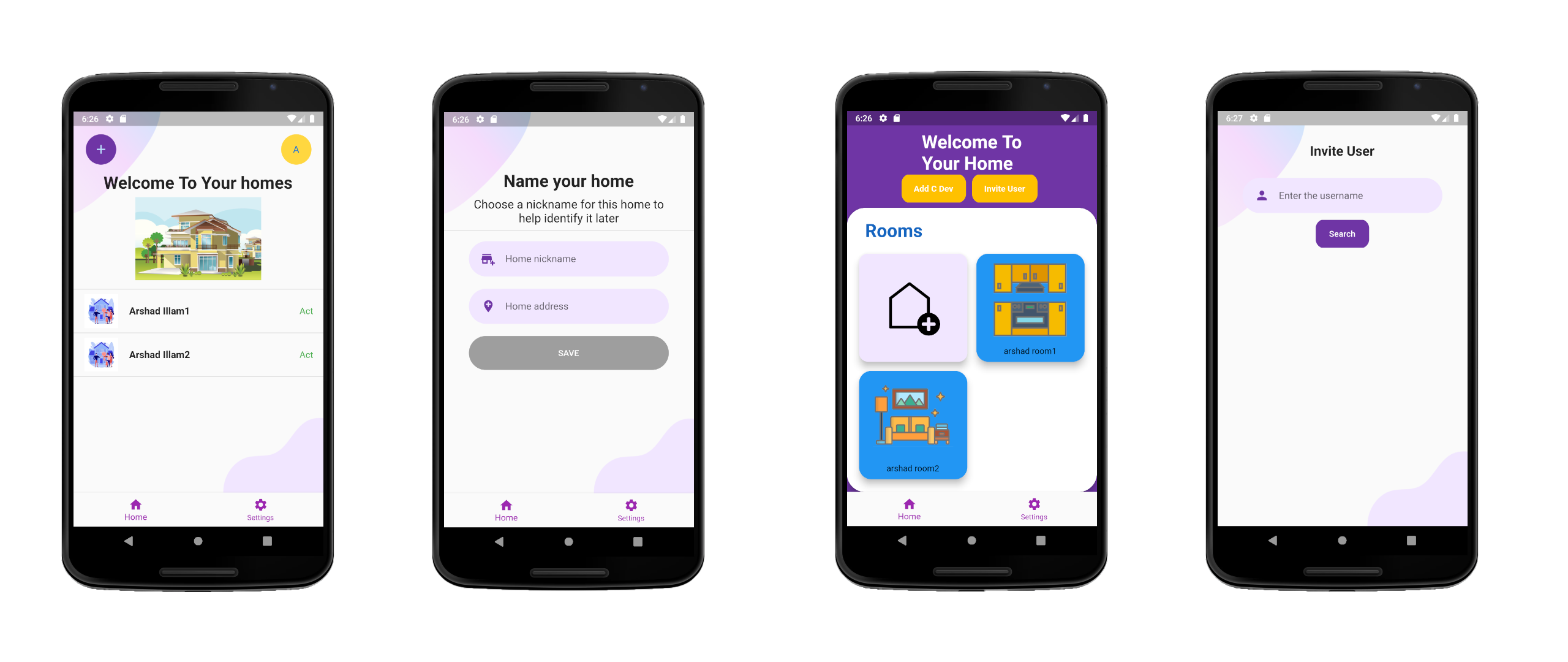
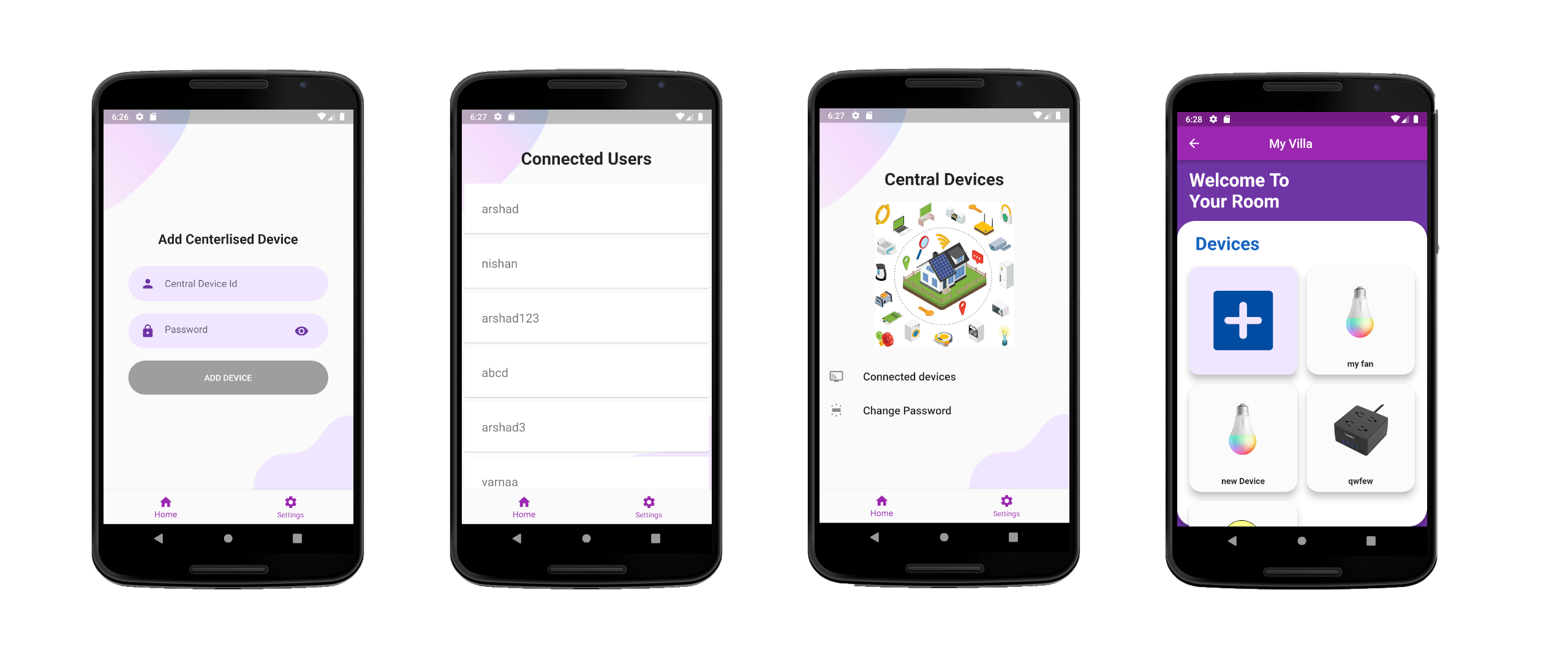
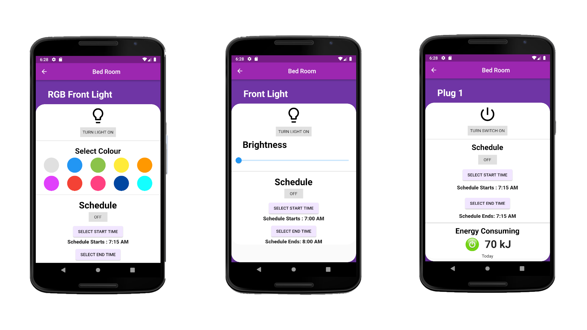
UI DESIGN
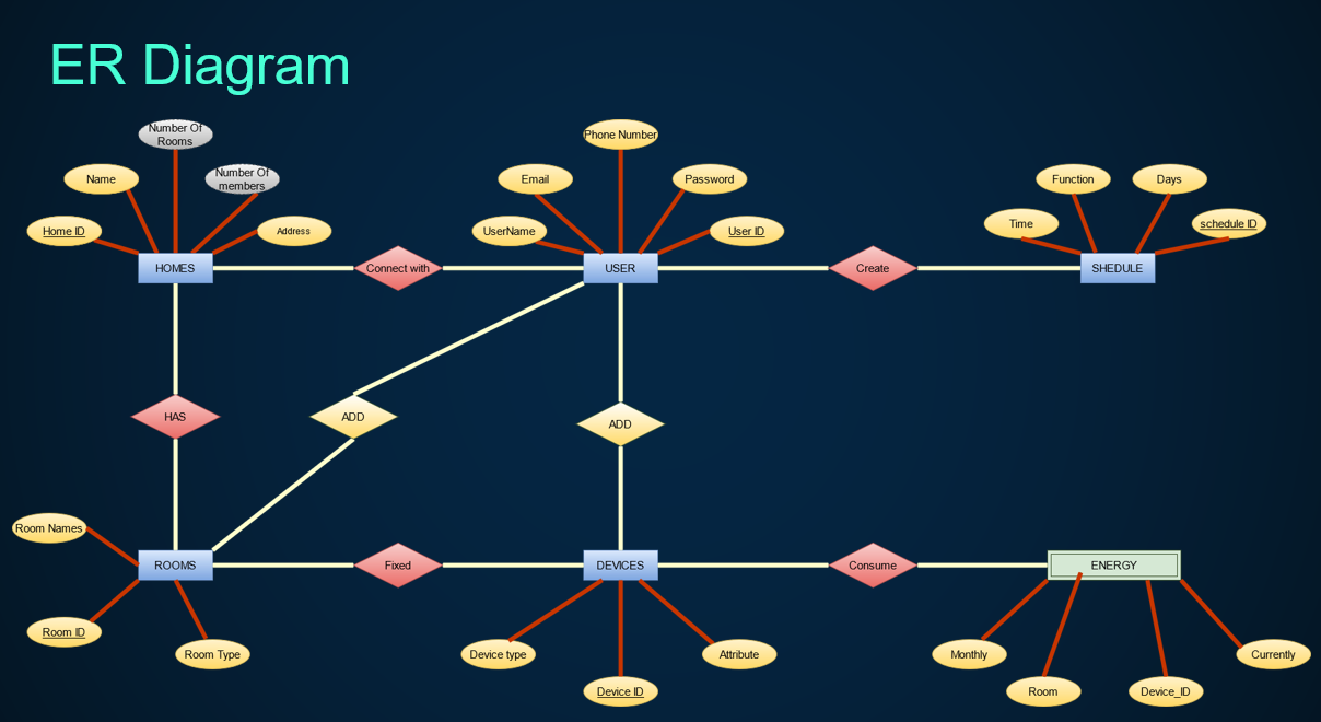
ER Diagram
Hardware Model
This our Hardware model of our project. These are the hardware componets we planned to use:
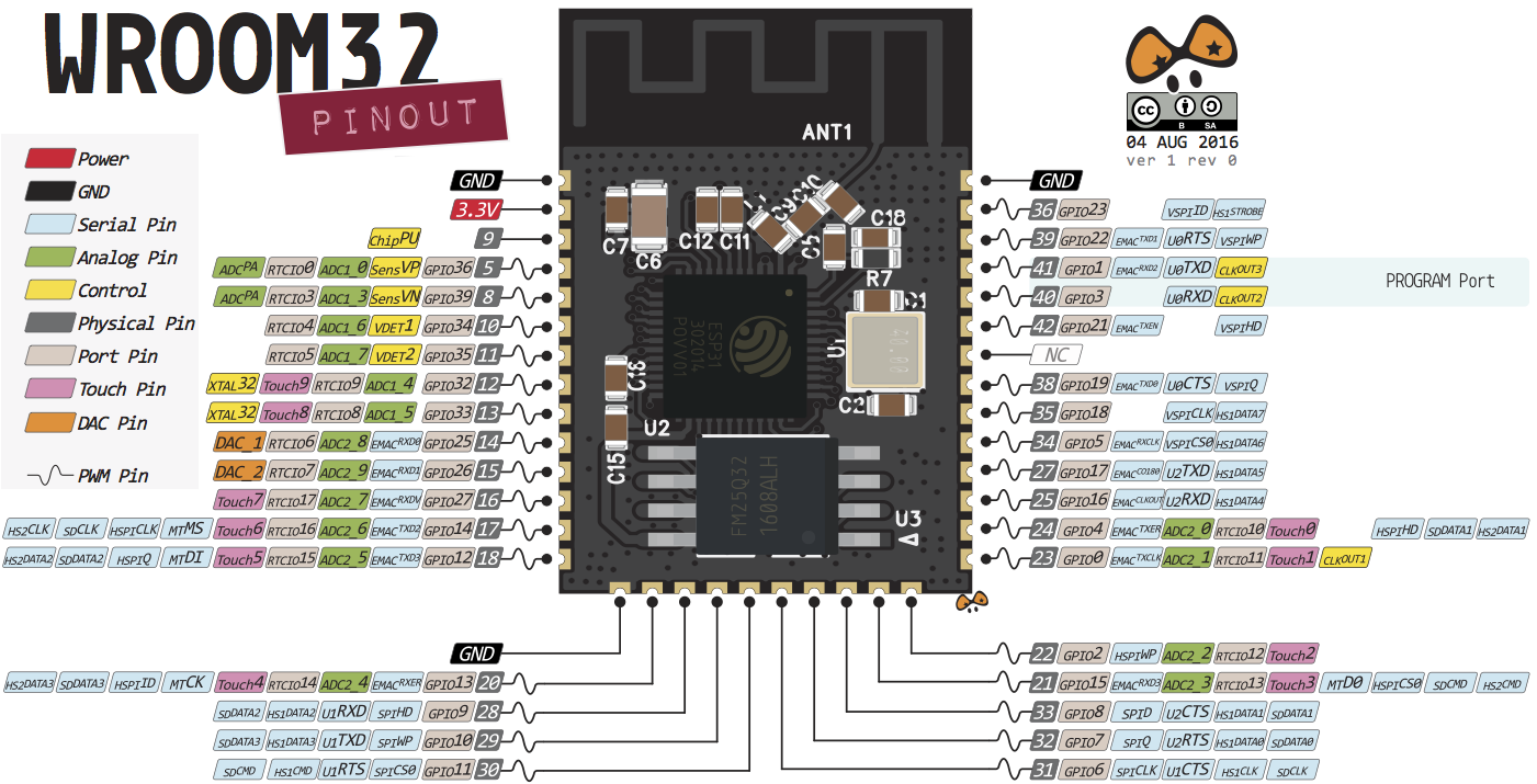
NodeMCU32S
NodeMCU32S is development board which is embeded with the esp32 micro
controller which
so small but powerfull. It's the perfect controller for our project because it's
cheap, it already
comes with the wifi module and it has many features.
Feature of the ESP32:
- 18 Analog to DC converter
- 3 SPI interfaces
- 3 UART interfaces
- 2 I2C interfaces
- 16 PWM output channels
- 2 DAC
- 2 I2S interfaces
- 10 Capacitive sensing GPIOs
Hardware Model
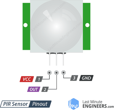
PIR Sensor
Passive Infrared Sensor commanly known as Proximity motion
sensor. PIR sensors are
used to detect the movements. It functioning by absorbing the IR rays emits
from the objects.
Humans and animals emit the IR radiation other than that the hot objects
also emits the IR rays so
IR sensor detect the movements of the objects. Many variety of sensors in
the market they vary
with price, sensitivity and range. For this project we HC-SR501. Because it
mid range wide, angle,
good sensitivity and cheap
Referense Link
Hardware Model
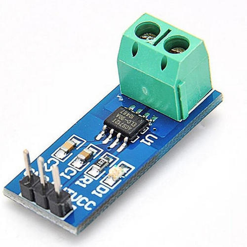
Current Sensor
ACS 712 Current sensor used to measure the current using the
Hall-Effect princile.
Many current sensors are in the market but we selected this because of it's
size and accuraccy.
it's so small but it can measure up to 30A and the energy wastage is
negligible.
- 30 A module
- 5V Operating Voltage
- Scale factor 100 mV per Amp
Referense Link
Hardware Model
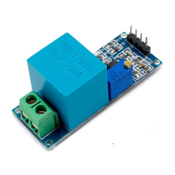
Voltage Sensor
ZMPT101b is a voltage sensor which accurate and small in size
and best suited for
the
IoT developments.
- Measure up to 250 V
- Operating Voltage: DC 5V-30V
- Output Signal: Analog 0-5V
Referense Link
Hardware Model
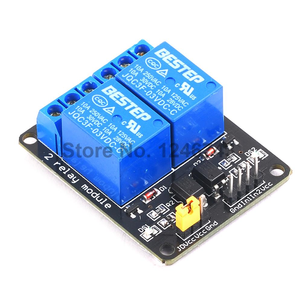
3-3.3V Relay
Relay is an electrically operated switch. It consists of a set of input
terminals for a
signal or multiple control signals, and a set of operating contact
terminals. The
switch may have any number of contacts or multiple contact forms, such as
make
contacts, break contacts, or combinations thereof.
Relay are used where it is necessary to control a circuit by an independent
low-power
signal, or where several circuits must be controlled by one signal.
Referense
Link
Hardware Model
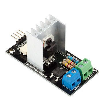
AC Dimmer
The AC Dimmer is designed to control the alternating current voltage,
which can transfer current up to 400V/8А. In most cases, Dimmer is used to
turning the power ON/OFF for lamps or heating elements, it can also be used
in
fans, pumps, air cleaners, e.t.c. Lately, Dimmer has become an often-used
decision
for smart home systems. For example, when you need to smoothly change the
light brightness.
- Power : up to 400V/600V (8A~24A)
- Operating Voltage 0 - 3.3 V
- Current signal > 10mA
Referense Link
Hardware Model
CAD MODEL
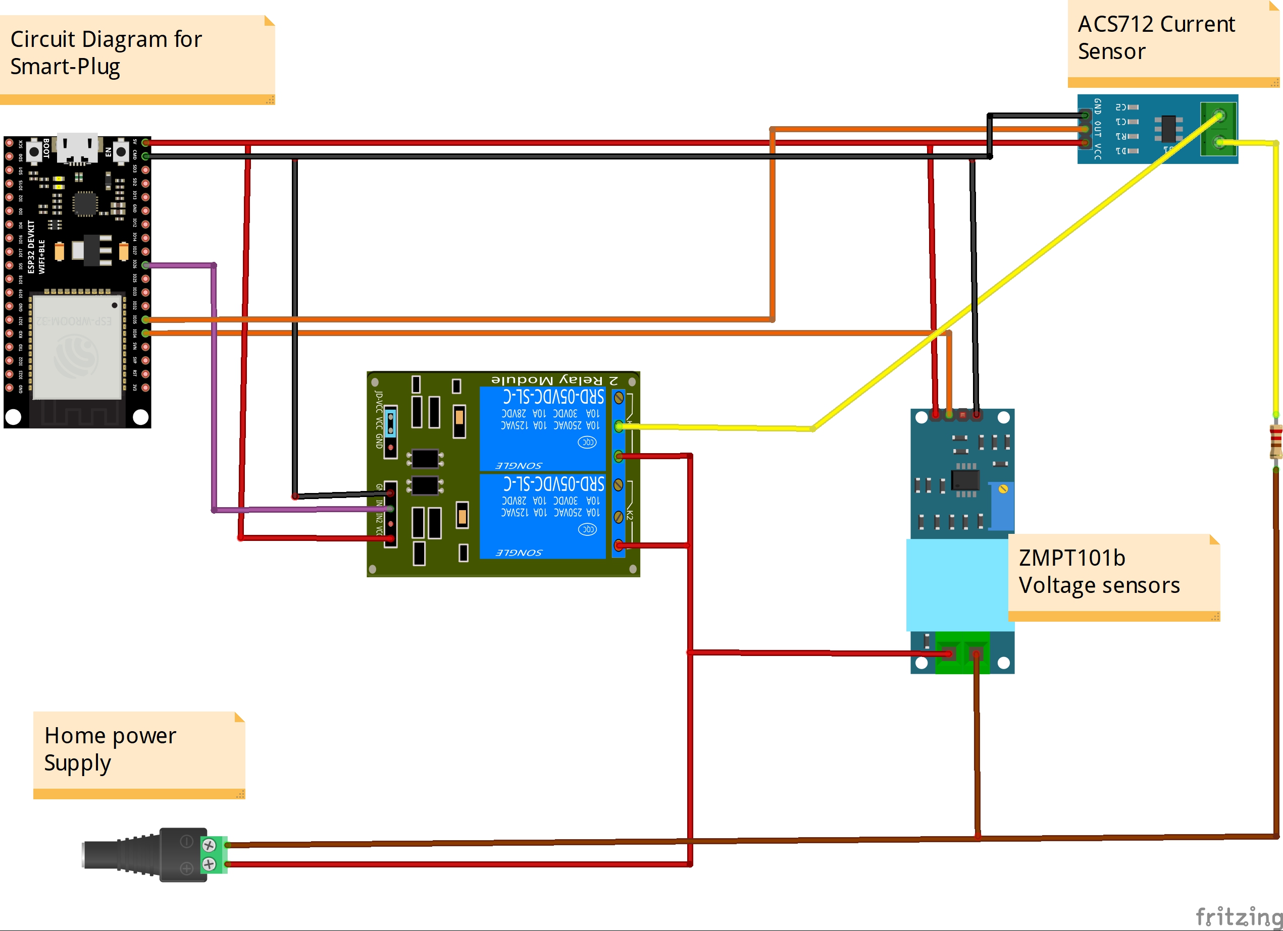
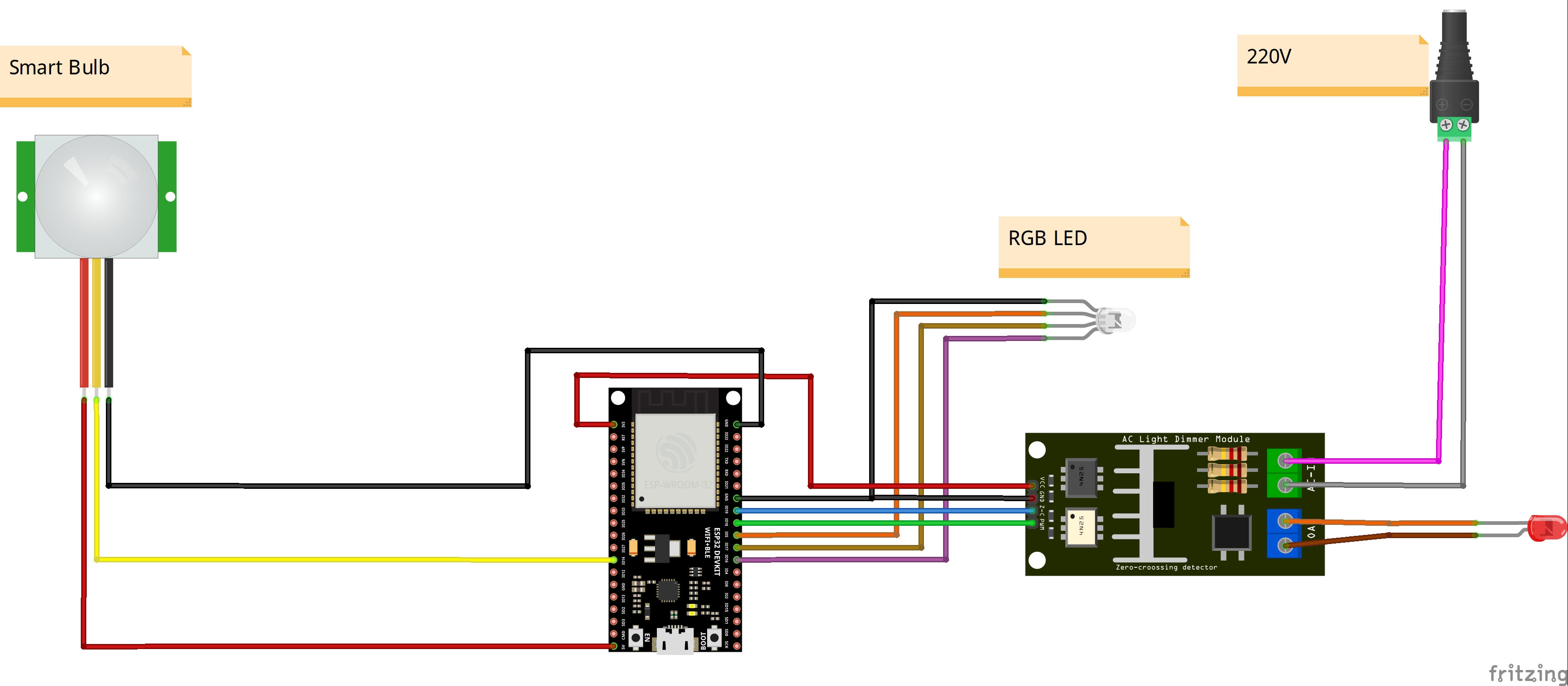
Circuit Diagram
Circuit Diagram of the Smart Plug. Here the led denotes the Load.
Circuit Diagram
Circuit Diagram of the Smart Bulb. Here the led denotes the Bulb.

TESTING DEMO
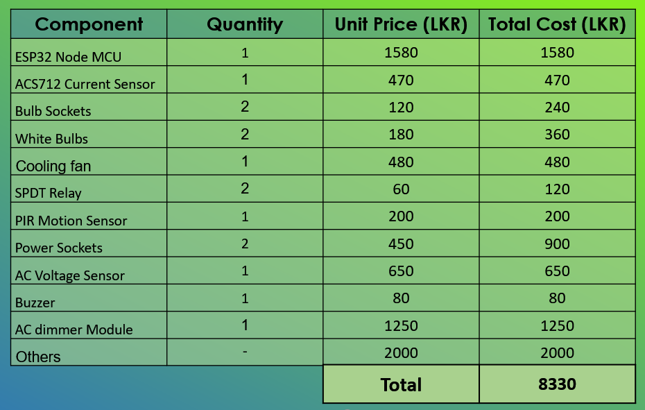
Budget of our Project
This is the budget of our project
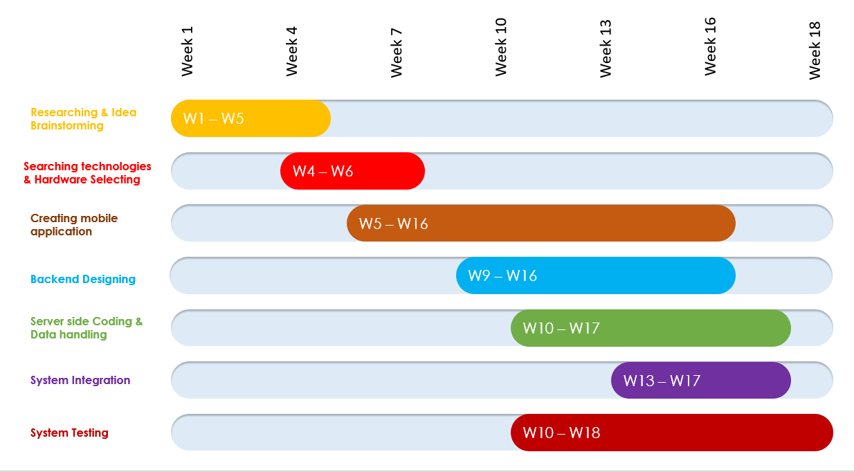
Timeline
Team Members


![]() Arshad MRM E/17/015
Arshad MRM E/17/015


![]() Nishankar S E/17/230
Nishankar S E/17/230

![]() Varnaraj N E/17/358
Varnaraj N E/17/358
Supervisor

![]() Dr. Isuru Nawinne
Dr. Isuru Nawinne

![]() Dr. Mahanama Wickramasinghe
Dr. Mahanama Wickramasinghe
![]()
Step in to the future
© Copyright digitalHuT. All Rights Reserved