Click the thumbnail above to watch the video lecture on YouTube
1.1 Introduction
This lecture introduces the fundamental concepts of computer system abstractions, exploring the relationship between hardware and software while providing an overview of the lecture series structure and topics. We examine how computer systems are built as hierarchies of abstractions, each hiding complexity while providing services to the levels above.
1.2 The Big Picture of Computer Systems
1.2.1 Cross-Section of a Computer System (Top to Bottom)
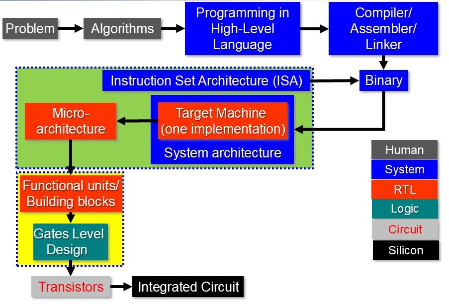 The diagram above illustrates the complete hierarchy from problems and algorithms at the human level, through the compilation toolchain (Compiler/Assembler/Linker), down to the ISA, microarchitecture (RTL), functional units, logic gates, transistors, and finally the silicon substrate. Each colored layer represents a different abstraction level.
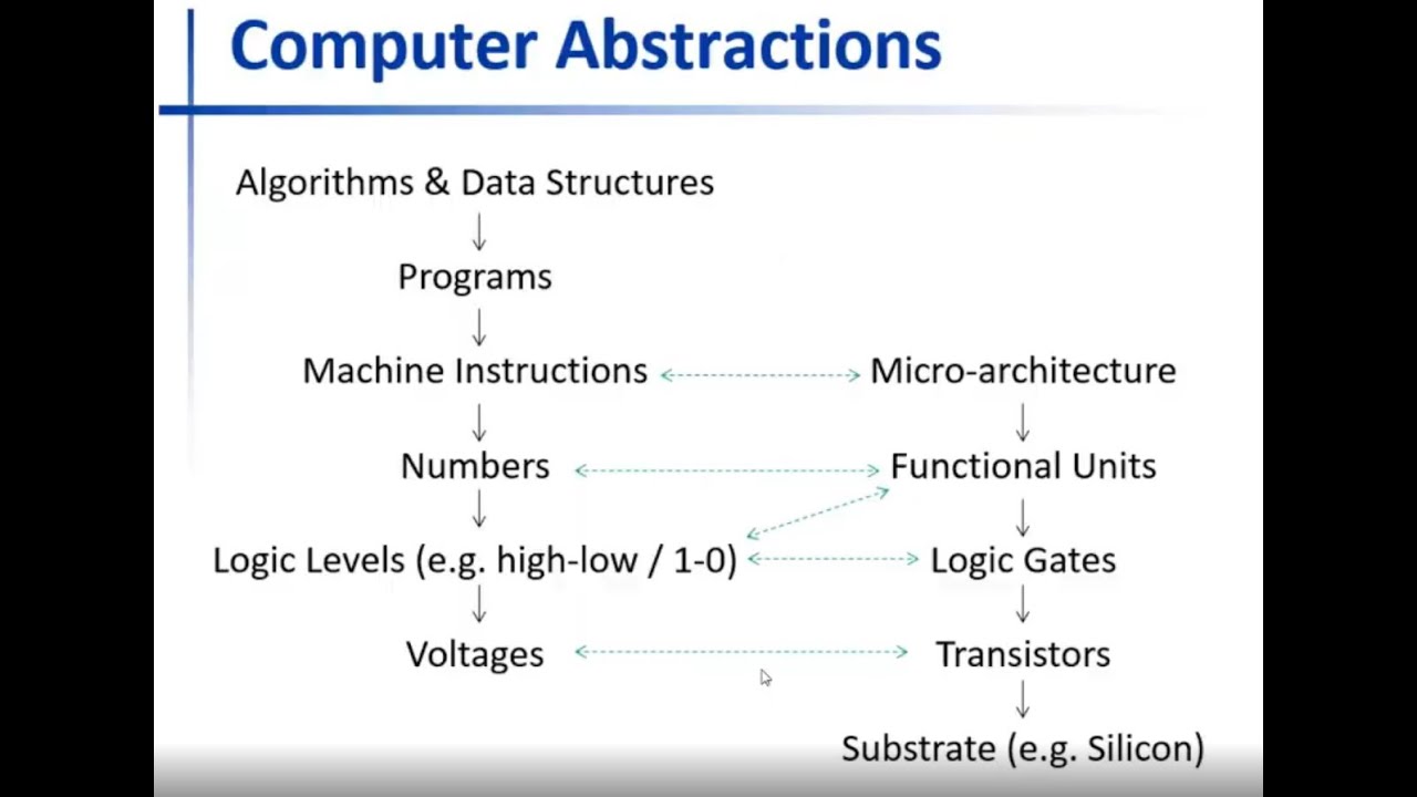
1.2.2 Human-Related Level (Gray)
- Problems: Real-world challenges to be solved
- Algorithms: Step-by-step solutions to problems
- Programming Languages: Tools to express algorithms
1.2.3 System Level (Blue)
- Compilers: Translate high-level code to assembly
- Assemblers: Convert assembly to machine code
- Linkers: Combine programs with libraries
- Instruction Set Architecture (ISA): The hardware-software interface
1.2.4 RTL (Register Transfer Level) - Red/Orange
- Microarchitecture: The processor's internal organization
- Functional Units: Building blocks that perform operations
1.2.5 Logic Level (Green)
- Gate-level circuits: Digital logic implementations
- Logic gates: AND, OR, NAND, NOR, XOR, etc.
1.2.6 Circuit Level (Light Gray)
- Transistors: BJT, CMOS devices
- Voltage levels and currents: Electrical signals
1.2.7 Substrate Level (Black)
- Semiconductors: Base materials
- P-type and N-type semiconductors: Doped materials
- Electron currents: Physical phenomena
1.2.8 Purpose of Computer Systems
- Built to solve problems (like any engineering system)
- Process: Problems → Algorithms → Programs → Machine Code → Execution
- Each level provides services to the level above
- Each level hides complexity from the level above
1.3 Instruction Set Architecture (ISA) - The Key Interface
1.3.1 What is an ISA?
Definition:
- A specification defining what the computer will understand
- Contains a list of basic instructions the processor can execute
- Examples: ARM version 8, MIPS, x86
- The critical interface between hardware and software
1.3.2 Example Instructions in an ISA
- Add two numbers together
- Subtract one number from another
- Multiply two numbers
- Load a number from memory into CPU
- Store a number from CPU into memory
- All basic operations are well-defined in the ISA
1.3.3 Importance of ISA
- Microarchitecture is built to support a specific ISA
- Programs must be written using instructions from the target ISA
- Compilers translate high-level code to ISA instructions
- ISA is the key point combining software with hardware
1.4 From Problem to Execution - The Translation Chain
1.4.1 High-Level Process
1.4.2 Tool Chain Components
Compiler
- Function: Converts high-level language to assembly language
- Complexity: Complex task requiring optimization
- Optimizations: Performance and memory optimizations
- Example: ARM GCC compiler for ARM processors
Assembler
- Function: Converts assembly to machine code
- Integration: Built into the tool chain
- Output: Produces binary image (ones and zeros)
Linker
- Function: Combines program with libraries
- Output: Creates final executable
- Process: Resolves external references
1.4.3 Architecture-Specific Compilation
- If targeting ARM processor: Use ARM toolchain
- If targeting MIPS processor: Use MIPS toolchain
- Machine code is specific to the target ISA
- Cannot run ARM code on MIPS processor directly
1.5 Writing Programs at Different Levels
1.5.1 Machine Code (Binary)
Characteristics:
- Ones and zeros
- Directly executable by processor
- Very difficult for humans to write
- Error-prone and time-consuming
1.5.2 Assembly Language
Characteristics:
- Textual representation of machine instructions
- Example:
ADD R1, R2, R3instead of binary - One-to-one mapping with machine code
- Easier than machine code but still difficult for large programs
- Used in CO224 labs for ARM assembly programming
1.5.3 High-Level Languages (C, Python, etc.)
Characteristics:
- Easier to write and understand
- Good for large programs and general-purpose applications
- Requires compiler to translate to assembly/machine code
- Provides abstractions hiding hardware details
1.6 Microarchitecture Details
1.6.1 What is Microarchitecture?
Definition:
- A digital logic circuit built to support a given ISA
- Processes binary image (machine code)
- Understands meaning of ones and zeros
- Performs operations in actual hardware
1.6.2 Hierarchy of Microarchitecture Components
Microarchitecture Level
- Manipulates instructions
- Built using functional units and gate-level logic
Functional Units Level
- Purpose: Manipulates numbers
- Examples:
- Adders (ripple carry, half adders, full adders)
- Multiplexers
- Encoders
- Decoders
- Built using logic gates
Logic Gate Level
- Purpose: Manipulates logic levels (1s and 0s, HIGH and LOW)
- Gates: AND, OR, NAND, NOR, XOR, NOT
- Built using transistors
Transistor Level
- Purpose: Manipulates voltages and currents
- Types: BJT, CMOS
- Built using semiconductors
Semiconductor Level
- Deals with electron currents
- P-type and N-type semiconductors
- Combined to create transistors
1.7 Abstraction Concept
1.7.1 What is an Abstraction?
Key Principles:
- A conceptual entity hiding internal details
- Provides interface to higher levels
- Hides complexity underneath
- Each level doesn't worry about details above or below
- Encapsulates details and defines specific characteristics
1.7.2 Hardware Abstraction Hierarchy (Bottom to Top)
1. Substrate (Silicon, Germanium)
- Base semiconductor material
2. Transistors
- Built using semiconductor substrate
- Deal with voltage levels
3. Logic Gates
- Built using transistors
- Deal with logic levels (HIGH/LOW, 1/0)
4. Functional Units
- Built using logic gates
- Deal with numbers
- Examples: Adders, multiplexers
5. Microarchitecture
- Built using functional units and logic elements
- Deals with instructions
- Understands machine instructions
1.7.3 Software Abstraction Hierarchy (Bottom to Top)
1. Machine Instructions (Binary)
- Ones and zeros
- Collection of logic levels
- Executable by microarchitecture
2. Assembly Instructions
- Textual representation of machine code
- One-to-one mapping with machine instructions
- Easier for humans to read
3. Programs / Source Code
- Written in high-level languages
- Collections of instructions
- Represent algorithms
4. Algorithms and Data Structures
- Conceptual entities
- Represent solutions to problems
- Highest level abstraction
1.7.4 Relationships Between Hardware and Software Abstractions
Voltage Levels ↔ Logic Levels
- Logic 1: Higher voltage range (e.g., 4-5V)
- Logic 0: Lower voltage range (e.g., 0-1V)
- Ranges depend on transistor type (TTL vs CMOS)
Logic Levels ↔ Numbers
- Numbers represented as strings of binary digits
- Collections of logic levels form numbers
Numbers ↔ Instructions
- Instructions represented as binary numbers
- Microarchitecture interprets these numbers
Summary of Relationships
- Transistors ↔ Voltages (deal with)
- Logic Gates ↔ Logic Levels (deal with)
- Functional Units ↔ Numbers (deal with)
- Microarchitecture ↔ Instructions (understands)
1.7.5 Complete System
- All abstractions together create "the computer"
- Can deconstruct algorithm down to voltage levels
- Can deconstruct microarchitecture down to silicon
- Tight coupling between hardware and software abstractions
- Computer systems are everywhere due to these abstractions
1.8 Performance Theme
1.8.1 Throughout the Lecture Series
Performance is a recurring theme that will be touched upon in every topic:
- How efficiently can CPU do things?
- How fast can operations be performed?
- How can performance be improved?
- Hardware-based improvements
- Software-based improvements
Key Takeaways
- Computer systems are built as hierarchies of abstractions
- Each abstraction level hides complexity and provides services to levels above
- Instruction Set Architecture (ISA) is the critical interface between hardware and software
- Hardware hierarchy: Substrate → Transistors → Gates → Functional Units → Microarchitecture
- Software hierarchy: Machine Code → Assembly → Programs → Algorithms
- Tight coupling exists between hardware and software abstractions
- Voltages → Logic Levels → Numbers → Instructions (relationships between levels)
- Covers ISA, microarchitecture, memory hierarchy, and system organization
- Labs involve ARM assembly programming and building processor using Verilog
- Understanding the complete system picture is essential for computer engineers
- All computer systems, regardless of complexity, are built on these fundamental abstractions
- Performance optimization is a central theme throughout the lecture series
Summary
Computer systems represent one of the most sophisticated examples of hierarchical abstraction in engineering. From the physical movement of electrons in semiconductors to high-level programming languages, each layer builds upon and hides the complexity of the layers below. The Instruction Set Architecture serves as the critical bridge between hardware and software, enabling programmers to write code without worrying about transistor-level details while allowing hardware designers to optimize implementations without breaking software compatibility.
Throughout this lecture series, we will explore these abstractions in depth, learning not just what they are, but why they exist and how they enable the remarkable computing capabilities we rely on every day. By understanding both hardware and software perspectives, computer engineers gain the ability to design, optimize, and innovate across the entire computing stack.