Click the thumbnail above to watch the video lecture on YouTube
5.1 Introduction
This lecture delves into how computers represent and manipulate data at the binary level. We explore number systems, two's complement representation for signed integers, instruction encoding formats in ARM assembly, and logical operations for bit manipulation. Understanding these fundamentals is essential for programming efficiently in assembly language and comprehending how processors execute arithmetic and logical operations.
5.2 Number Representation Systems
5.2.1 Unsigned Binary Integers
Binary System Basics
- Base-2 number system using digits 0 and 1
- Each bit position represents a power of 2
- Rightmost bit is least significant (LSB)
- Leftmost bit is most significant (MSB)
Place Value Calculation
N-Bit Unsigned Range
- N bits can represent 2^N different values
- Range: 0 to (2^N - 1)
- 8 bits: 0 to 255
- 32 bits: 0 to 4,294,967,295
Binary to Decimal Conversion
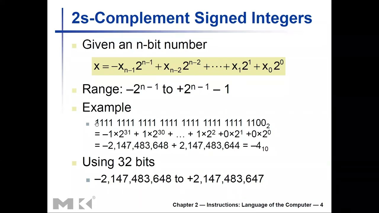
5.2.2 Two's Complement Representation
Purpose of Two's Complement
- Represents both positive and negative integers
- Simplifies hardware (same adder for signed/unsigned)
- Unique zero representation
- Natural overflow behavior
Sign Bit
- MSB indicates sign
- MSB = 0: Positive number
- MSB = 1: Negative number
Positive Numbers
- Same as unsigned binary
- MSB is always 0
- Example: +5 in 8 bits = 00000101
Negative Numbers
- Represented as 2^N - |value|
- Example: -5 in 8 bits:
Two's Complement Conversion
Method 1 (Invert and Add):
- Write positive value in binary
- Invert all bits (0→1, 1→0)
- Add 1 to result
Example: -5 in 8 bits
+5:        00000101
Invert:    11111010
Add 1:     11111011  (this is -5)
Method 2 (Subtraction):
N-Bit Signed Range
- Range: -(2^(N-1)) to +(2^(N-1) - 1)
- 8 bits: -128 to +127
- 32 bits: -2,147,483,648 to +2,147,483,647
Special Cases
- Zero: 00000000 (unique representation)
- Most negative: 10000000 (-128 in 8 bits)
- Has no positive counterpart!
- Negating gives overflow
5.2.3 Sign Extension
Purpose
- Extend smaller signed value to larger width
- Preserve numerical value
- Required when loading bytes/halfwords into 32-bit registers
Process
- Replicate the sign bit (MSB) to fill new bits
- Preserves positive/negative value
Examples
8-bit to 32-bit:
00000101 (+5) → 00000000 00000000 00000000 00000101 (+5)
11111011 (-5) → 11111111 11111111 11111111 11111011 (-5)
ARM Instructions for Sign Extension
- LDRH: Load halfword (16 bits), zero-extend to 32 bits
- LDRSH: Load signed halfword, sign-extend to 32 bits
- LDRB: Load byte (8 bits), zero-extend to 32 bits
- LDRSB: Load signed byte, sign-extend to 32 bits
Example Usage
LDRH R0, [R1]     ; R0 = 0x0000ABCD (zero-extended)
LDRSH R0, [R1]    ; R0 = 0xFFFFABCD (sign-extended if bit 15 = 1)
LDRB R0, [R1]     ; R0 = 0x000000AB (zero-extended)
LDRSB R0, [R1]    ; R0 = 0xFFFFFFAB (sign-extended if bit 7 = 1)
5.2.4 Hexadecimal Notation
Why Hexadecimal?
- Compact representation of binary
- One hex digit = 4 binary bits
- Easier to read than long binary strings
- Common in programming and debugging
Hex Digits
| Binary | Hex | Decimal |
|---|---|---|
| 0000 | 0 | 0 |
| 0001 | 1 | 1 |
| 0010 | 2 | 2 |
| 0011 | 3 | 3 |
| 0100 | 4 | 4 |
| 0101 | 5 | 5 |
| 0110 | 6 | 6 |
| 0111 | 7 | 7 |
| 1000 | 8 | 8 |
| 1001 | 9 | 9 |
| 1010 | A | 10 |
| 1011 | B | 11 |
| 1100 | C | 12 |
| 1101 | D | 13 |
| 1110 | E | 14 |
| 1111 | F | 15 |
Conversion Examples
Binary: 1011 0110 1101 0010
Hex:      B    6    D    2
Result: 0xB6D2

Hex: 0x3F
Binary: 0011 1111
Decimal: 63
ARM Hexadecimal Usage
MOV R0, #0xFF        ; R0 = 255
MOV R1, #0x100       ; R1 = 256
LDR R2, =0xDEADBEEF  ; R2 = 3735928559
5.3 ARM Instruction Encoding
5.3.1 Fixed-Length Instructions
32-Bit Instruction Format
- Every ARM instruction is exactly 32 bits
- Simplifies instruction fetch and decode
- Enables efficient pipelining
Advantages
- Predictable instruction boundaries
- Simple PC increment (always +4)
- Fast decode logic
Trade-offs
- Some instructions may "waste" bits
- Immediate values limited in size
- Code density lower than variable-length (e.g., x86)
5.3.2 Data Processing Instruction Format
Format Structure
[Cond][00][I][Opcode][S][Rn][Rd][Operand2]
4-bit 2  1   4-bit   1  4   4   12-bit
Field Descriptions
Condition (4 bits, bits 28-31)
- Conditional execution feature
- 0000 = EQ (equal, Z=1)
- 0001 = NE (not equal, Z=0)
- 1010 = GE (greater or equal, signed)
- 1110 = AL (always execute, default)
I bit (bit 25)
- 0 = Operand2 is register
- 1 = Operand2 is immediate value
Opcode (4 bits, bits 21-24)
- Specifies operation (AND, EOR, SUB, ADD, etc.)
- 0100 = ADD
- 0010 = SUB
- 0000 = AND
- 1100 = ORR
S bit (bit 20)
- 0 = Don't update condition flags
- 1 = Update flags (CPSR)
Rn (4 bits, bits 16-19)
- First operand register number
- 0000 = R0, 0001 = R1, etc.
Rd (4 bits, bits 12-15)
- Destination register number
Operand2 (12 bits, bits 0-11)
- If I=0: Shift amount and second register
- If I=1: 8-bit immediate + 4-bit rotation
Example: ADD R0, R1, R2
Encoding fields:
  Cond: 1110 (always)
  I: 0 (register operand)
  Opcode: 0100 (ADD)
  S: 0 (don't update flags)
  Rn: 0001 (R1)
  Rd: 0000 (R0)
  Operand2: 0002 (R2, no shift)

Result: 0xE0810002
5.3.3 Data Transfer Instruction Format
Format Structure
[Cond][01][I][P][U][B][W][L][Rn][Rd][Offset]
4-bit 2  1  1  1  1  1  1  4   4   12-bit
Key Fields
L bit (bit 20)
- 0 = Store (STR)
- 1 = Load (LDR)
B bit (bit 22)
- 0 = Word transfer (32 bits)
- 1 = Byte transfer (8 bits)
P bit (bit 24)
- 0 = Post-indexed addressing
- 1 = Pre-indexed or offset addressing
U bit (bit 23)
- 0 = Subtract offset from base
- 1 = Add offset to base
W bit (bit 21)
- 0 = No write-back
- 1 = Write-back (update base register)
Rn (base register)
- Contains memory address or base address
Rd (data register)
- For Load: Destination register
- For Store: Source register
Offset (12 bits)
- Memory address offset
- Can be immediate or register
Example: LDR R0, [R1, #4]
Encoding fields:
  Cond: 1110 (always)
  L: 1 (load)
  B: 0 (word)
  P: 1 (offset addressing)
  U: 1 (add offset)
  Rn: 0001 (R1)
  Rd: 0000 (R0)
  Offset: 004 (immediate 4)

Result: 0xE5910004
5.3.4 Immediate Value Encoding
Challenge
- 32-bit instruction must fit: opcode, registers, immediate
- Cannot fit full 32-bit immediate
ARM Solution: 8-bit + 4-bit Rotation
- Immediate field: 12 bits total
- Lower 8 bits: Immediate value (0-255)
- Upper 4 bits: Rotation amount (0-15)
- Rotation: Right by (2 × rotation field) bits
Calculation
Examples
Immediate=0xFF, Rotation=0:
Value = 0xFF ROR 0 = 0x000000FF

Immediate=0xFF, Rotation=8:
Value = 0xFF ROR 16 = 0x00FF0000

Immediate=0xFF, Rotation=12:
Value = 0xFF ROR 24 = 0xFF000000
Allowed Immediates
- Not all 32-bit values can be encoded
- Valid: 0xFF, 0xFF00, 0xFF0000, 0xFF000000
- Valid: 0xFF000000FF (rotation wraps around)
- Invalid: 0x123 (cannot be formed by rotation)
Assembler Handling
- Assembler checks if immediate is valid
- Gives error if immediate cannot be encoded
- Use LDR pseudo-instruction for arbitrary values:
LDR R0, =0x12345678 ; Loads from literal pool
5.4 Logical Operations
5.4.1 Bitwise AND
Operation
- Performs logical AND on each bit pair
- Result bit = 1 only if both input bits are 1
Truth Table
| A | B | A AND B |
|---|---|---|
| 0 | 0 | 0 |
| 0 | 1 | 0 |
| 1 | 0 | 0 |
| 1 | 1 | 1 |
ARM Instruction
AND Rd, Rn, Rm       ; Rd = Rn AND Rm
AND Rd, Rn, #imm     ; Rd = Rn AND immediate
Common Uses
Bit Masking (Extract Specific Bits)
; Extract lower 8 bits of R1
MOV R0, R1
AND R0, R0, #0xFF    ; R0 = R1 & 0xFF (keep bits 0-7)

; Extract bits 8-15
MOV R0, R1
AND R0, R0, #0xFF00  ; R0 = R1 & 0xFF00 (keep bits 8-15)
Clearing Specific Bits
; Clear bit 5 of R1
AND R1, R1, #0xFFFFFFDF  ; Bit 5 mask: ~(1 << 5)
Checking if Bit Set
AND R2, R1, #0x80    ; Check if bit 7 is set
CMP R2, #0           ; Compare with zero
BEQ bit_clear        ; Branch if bit was clear
5.4.2 Bitwise OR
Operation
- Performs logical OR on each bit pair
- Result bit = 1 if either input bit is 1
Truth Table
| A | B | A OR B |
|---|---|---|
| 0 | 0 | 0 |
| 0 | 1 | 1 |
| 1 | 0 | 1 |
| 1 | 1 | 1 |
ARM Instruction
ORR Rd, Rn, Rm       ; Rd = Rn OR Rm (ORR in ARM)
ORR Rd, Rn, #imm     ; Rd = Rn OR immediate
Common Uses
Setting Specific Bits
; Set bit 3 of R1
ORR R1, R1, #0x08    ; Bit 3 mask: (1 << 3) = 0x08

; Set bits 4 and 5
ORR R1, R1, #0x30    ; Mask: 0x30 = 0b00110000
Combining Values
; Combine lower byte of R1 with upper bytes of R2
AND R1, R1, #0xFF        ; Keep only lower byte
AND R2, R2, #0xFFFFFF00  ; Keep only upper bytes
ORR R0, R1, R2           ; Combine
5.4.3 Bitwise XOR (Exclusive OR)
Operation
- Performs logical XOR on each bit pair
- Result bit = 1 if input bits differ
Truth Table
| A | B | A XOR B |
|---|---|---|
| 0 | 0 | 0 |
| 0 | 1 | 1 |
| 1 | 0 | 1 |
| 1 | 1 | 0 |
ARM Instruction
EOR Rd, Rn, Rm       ; Rd = Rn EOR Rm (EOR in ARM)
EOR Rd, Rn, #imm     ; Rd = Rn EOR immediate
Common Uses
Toggling Specific Bits
; Toggle bit 2 of R1
EOR R1, R1, #0x04    ; Bit 2 mask: (1 << 2)
; If bit was 0, becomes 1; if was 1, becomes 0
Fast Zero
EOR R0, R0, R0 ; R0 = 0 (XOR with itself)
Comparison
; Check if R1 and R2 are equal
EOR R3, R1, R2       ; R3 = R1 XOR R2
CMP R3, #0           ; If R3 = 0, R1 == R2
BEQ values_equal
Swapping Without Temporary
; Swap R0 and R1 without using another register
EOR R0, R0, R1
EOR R1, R0, R1
EOR R0, R0, R1
; Now R0 and R1 are swapped
5.4.4 Bitwise NOT
Operation
- Inverts all bits (0→1, 1→0)
- Also called complement
ARM Instruction
MVN Rd, Rm           ; Rd = NOT Rm (Move Not)
MVN Rd, #imm         ; Rd = NOT immediate
Common Uses
Creating Bit Masks
; Create mask with all bits set except bit 3
MOV R0, #0x08        ; 0x08 = 0b00001000
MVN R1, R0           ; R1 = 0xFFFFFFF7 (all except bit 3)
Negation (with ADD)
; Negate R1 (two's complement)
MVN R1, R1           ; Invert all bits
ADD R1, R1, #1       ; Add 1
; Now R1 = -R1 (original)
5.4.5 Shift Operations
Logical Shift Left (LSL)
LSL Rd, Rn, #shift   ; Rd = Rn << shift
MOV Rd, Rn, LSL #shift
- Shifts bits left, fills right with zeros
- Each shift left multiplies by 2
- Example: 0b00001010 LSL 2 = 0b00101000
Logical Shift Right (LSR)
LSR Rd, Rn, #shift   ; Rd = Rn >> shift (unsigned)
MOV Rd, Rn, LSR #shift
- Shifts bits right, fills left with zeros
- Each shift right divides by 2 (unsigned)
- Example: 0b10100000 LSR 2 = 0b00101000
Arithmetic Shift Right (ASR)
ASR Rd, Rn, #shift ; Rd = Rn >> shift (signed)
- Shifts bits right, fills left with sign bit
- Preserves sign for signed division
- Example: 0b11110000 ASR 2 = 0b11111100 (sign preserved)
Rotate Right (ROR)
ROR Rd, Rn, #shift ; Rotate Rn right by shift
- Bits shifted out right reappear at left
- No information lost
- Example: 0b10000001 ROR 1 = 0b11000000
Common Shift Applications
Fast Multiplication/Division by Powers of 2
LSL R0, R1, #3       ; R0 = R1 × 8 (2^3)
LSR R0, R1, #2       ; R0 = R1 / 4 (unsigned)
ASR R0, R1, #2       ; R0 = R1 / 4 (signed)
Bit Extraction
; Extract bits 8-11 from R1
LSR R0, R1, #8       ; Shift bits 8-11 to bits 0-3
AND R0, R0, #0xF     ; Mask to keep only 4 bits
Bit Positioning
; Move bit 0 to bit 7
LSL R0, R1, #7       ; Shift left 7 positions
AND R0, R0, #0x80    ; Keep only bit 7
5.5 Practical Bit Manipulation Examples
5.5.1 Extracting Bit Fields
Extract bits 16-23
LSR R0, R1, #16      ; Shift right to position
AND R0, R0, #0xFF    ; Mask to 8 bits
Extract bits 4-9 (6 bits)
LSR R0, R1, #4       ; Shift to position 0
AND R0, R0, #0x3F    ; Mask to 6 bits (0b111111)
5.5.2 Setting and Clearing Bits
Set bits 8-15
ORR R1, R1, #0xFF00 ; Set bits 8-15
Clear bits 16-23
LDR R0, =0xFF00FFFF  ; Mask with bits 16-23 clear
AND R1, R1, R0       ; Clear bits 16-23 of R1
Toggle bits 0-7
EOR R1, R1, #0xFF ; Toggle lower byte
5.5.3 Checking Flags
Check if any of bits 4-7 are set
AND R2, R1, #0xF0    ; Mask bits 4-7
CMP R2, #0           ; Check if zero
BNE bits_set         ; Branch if any bit was set
Check if specific pattern matches
; Check if bits 8-11 are 0b1010
LSR R0, R1, #8       ; Position bits
AND R0, R0, #0xF     ; Mask 4 bits
CMP R0, #0xA         ; Compare with 0b1010
BEQ pattern_match
5.5.4 Color Packing/Unpacking
Pack RGB values (8 bits each)
; R0 = Red, R1 = Green, R2 = Blue
LSL R1, R1, #8       ; Green << 8
LSL R2, R2, #16      ; Blue << 16
ORR R3, R0, R1       ; Combine Red and Green
ORR R3, R3, R2       ; Combine with Blue
; R3 now contains 0x00BBGGRR
Unpack RGB values
; R0 contains 0x00BBGGRR
AND R1, R0, #0xFF      ; Extract Red
LSR R2, R0, #8
AND R2, R2, #0xFF      ; Extract Green
LSR R3, R0, #16
AND R3, R3, #0xFF      ; Extract Blue
Key Takeaways
- Unsigned binary integers represent values from 0 to 2^N - 1 using N bits.
- Two's complement represents signed integers, with MSB as sign bit and range -(2^(N-1)) to +(2^(N-1) - 1).
- Sign extension preserves value when expanding narrower signed values to wider registers.
- Hexadecimal notation provides compact representation with one hex digit per 4 binary bits.
- ARM instructions are fixed 32-bit length, simplifying fetch/decode but limiting immediate values.
- Data processing format includes condition, opcode, source/destination registers, and operand.
- Data transfer format specifies load/store, byte/word, addressing mode, and offset.
- Immediate encoding uses 8-bit value + 4-bit rotation, limiting which constants can be encoded directly.
- Bitwise AND used for masking (extracting specific bits) and clearing bits.
- Bitwise OR used for setting specific bits and combining values.
- Bitwise XOR used for toggling bits, fast zero, and comparisons.
- Shift operations enable fast multiplication/division by powers of 2 and bit positioning.
- Bit manipulation is fundamental for low-level programming, hardware control, and optimization.
- Understanding encoding helps write efficient assembly and debug machine code issues.
Summary
Number representation and instruction encoding form the foundation of low-level programming. Two's complement enables efficient signed arithmetic with simple hardware, while sign extension preserves values across different data sizes. ARM's fixed 32-bit instruction format provides regularity but imposes constraints on immediate values, solved through clever encoding schemes. Logical operations—AND, OR, XOR, and NOT—combined with shift operations, provide powerful tools for bit manipulation essential in systems programming, embedded development, and performance optimization. Mastering these concepts enables efficient assembly programming and deeper understanding of how high-level operations translate to machine instructions. These fundamentals prepare us for more complex topics including branching, function calls, and memory management.