Click the thumbnail above to watch the video lecture on YouTube
4.1 Introduction
This lecture introduces ARM assembly language programming, providing the foundation for understanding how high-level programs translate to machine code. We explore the ARM instruction set architecture (ISA), focusing on its RISC design philosophy, register organization, basic instruction formats, and the toolchain used for development. Understanding assembly language is essential for comprehending how processors execute programs and for optimizing performance-critical code.
4.2 ARM Architecture Overview
4.2.1 RISC Philosophy
Reduced Instruction Set Computer (RISC)
- Simple, uniform instruction format
- Fixed instruction length (32 bits in ARM)
- Load/store architecture (only LOAD/STORE access memory)
- Large number of general-purpose registers
- Few addressing modes
- Hardware simplicity for higher clock rates
Contrasted with CISC (Complex Instruction Set Computer)
| Feature | RISC | CISC |
|---|---|---|
| Instruction Format | Simple, uniform format | Variable-length instructions |
| Instruction Complexity | Simple instructions, more instructions per program | Complex operations |
| Memory Access | Load/store architecture (only LOAD/STORE access memory) | Memory operands in arithmetic operations |
| Registers | Large number of general-purpose registers | Fewer registers |
| Hardware Design | Hardware simplicity for higher clock rates | More complex hardware |
| Pipelining | Regular structure enables efficient pipelining | More difficult to pipeline |
ARM Design Principles
- Simplicity enables high performance
- Regular instruction encoding aids decoding
- Load/store architecture simplifies memory access
- Large register file reduces memory traffic
- Consistent design across instruction types
4.2.2 ARM Registers
General-Purpose Registers
- R0 to R15: 16 registers total
- 32 bits wide: Can hold integers, addresses, or data
- R0-R12: General computation and data storage
- R13 (SP): Stack Pointer - points to top of stack
- R14 (LR): Link Register - stores return address
- R15 (PC): Program Counter - address of next instruction
Register Usage Conventions
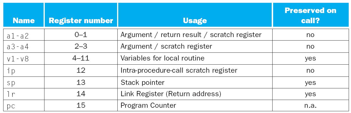
ARM Register Usage Conventions
R0-R3:   Argument/result registers
- Pass parameters to functions
- Return values from functions
- Scratch registers (not preserved)

R4-R11:  Local variable registers
- Must be preserved across function calls
- Callee saves/restores if used

R12:     Intra-procedure-call scratch register
- Can be corrupted by function calls
- Not preserved

R13 (SP): Stack Pointer
- Points to top of stack
- Must always be valid

R14 (LR): Link Register
- Stores return address on function call
- Contains address to return to

R15 (PC): Program Counter
- Always points to next instruction
- Modifying PC changes execution flow
Why So Many Registers?
- Reduces memory accesses (faster than cache/RAM)
- Enables register allocation by compiler
- Supports efficient function calls
- Improves performance through locality
4.2.3 Memory Organization
Little-Endian Byte Ordering
- Least significant byte at lowest address
- Example: 0x12345678 stored as:
Address:  [base+0] [base+1] [base+2] [base+3]
Content:     78       56       34       12
Word Alignment
- Words are 32 bits (4 bytes)
- Word addresses should be multiples of 4
- Accessing unaligned words may cause errors or slowdown
Address Space
- 32-bit addresses can access 2³² bytes = 4 GB
- Byte-addressable memory
- Instructions and data in same address space (Von Neumann architecture)
4.3 ARM Instruction Format
4.3.1 Instruction Structure
Fixed 32-Bit Length
- Every instruction exactly 32 bits
- Simplifies instruction fetch and decode
- Enables predictable pipeline operation
Typical Instruction Fields
[Condition][Opcode][Operands]
4 bits    varies   varies
Example: ADD Instruction
ADD R1, R2, R3 ; R1 = R2 + R3
Encoding includes:
- Condition code (usually "always")
- Opcode for ADD operation
- Destination register (R1)
- Source register 1 (R2)
- Source register 2 (R3)
4.3.2 Instruction Types
Data Processing Instructions
- Arithmetic: ADD, SUB, RSB (reverse subtract)
- Logical: AND, ORR, EOR (XOR), BIC (bit clear)
- Comparison: CMP, CMN, TST, TEQ
- Move: MOV, MVN (move negated)
- Shift/Rotate: LSL, LSR, ASR, ROR
Data Transfer Instructions
- Load: LDR (word), LDRB (byte), LDRH (halfword)
- Store: STR (word), STRB (byte), STRH (halfword)
- Multiple: LDM, STM (load/store multiple registers)
Control Flow Instructions
- Branch: B (unconditional), BEQ, BNE, BGE, BLT, etc.
- Function call: BL (branch and link)
- Return: MOV PC, LR
4.3.3 Operand Types
Register Operands
ADD R0, R1, R2 ; R0 = R1 + R2 (all registers)
Immediate Operands
ADD R0, R1, #5    ; R0 = R1 + 5 (# indicates immediate)
MOV R2, #100      ; R2 = 100
Immediate Value Constraints
- Limited to certain patterns due to 32-bit instruction encoding
- 8-bit immediate + 4-bit rotation
- Assembler warns if immediate cannot be encoded
Shifted Register Operands
ADD R0, R1, R2, LSL #2    ; R0 = R1 + (R2 << 2)
SUB R3, R4, R5, LSR #1    ; R3 = R4 - (R5 >> 1)
4.4 Basic ARM Instructions
4.4.1 Arithmetic Instructions
Addition
ADD Rd, Rn, Rm       ; Rd = Rn + Rm
ADD Rd, Rn, #imm     ; Rd = Rn + immediate
Examples:
ADD R0, R1, R2       ; R0 = R1 + R2
ADD R3, R3, #1       ; R3 = R3 + 1 (increment)
Subtraction
SUB Rd, Rn, Rm       ; Rd = Rn - Rm
SUB Rd, Rn, #imm     ; Rd = Rn - immediate
RSB Rd, Rn, #imm     ; Rd = immediate - Rn (reverse subtract)
Examples:
SUB R0, R1, R2       ; R0 = R1 - R2
SUB R4, R4, #10      ; R4 = R4 - 10 (decrement)
RSB R5, R6, #0       ; R5 = 0 - R6 (negate)
Multiplication (covered in later tutorials)
MUL Rd, Rn, Rm ; Rd = Rn × Rm (lower 32 bits)
4.4.2 Logical Instructions
AND Operation
AND Rd, Rn, Rm       ; Rd = Rn AND Rm
AND Rd, Rn, #imm     ; Rd = Rn AND immediate
Usage: Bit masking, clearing specific bits
Example:
AND R0, R0, #0xFF ; Keep only lower 8 bits
OR Operation
ORR Rd, Rn, Rm       ; Rd = Rn OR Rm (ORR in ARM)
ORR Rd, Rn, #imm     ; Rd = Rn OR immediate
Usage: Setting specific bits
Example:
ORR R1, R1, #0x80 ; Set bit 7
Exclusive OR
EOR Rd, Rn, Rm       ; Rd = Rn XOR Rm
EOR Rd, Rn, #imm     ; Rd = Rn XOR immediate
Usage: Toggling bits, fast comparison
Example:
EOR R2, R2, R2 ; R2 = 0 (XOR with itself)
Move and Move Not
MOV Rd, Rm           ; Rd = Rm
MOV Rd, #imm         ; Rd = immediate
MVN Rd, Rm           ; Rd = NOT Rm (bitwise complement)
Examples:
MOV R0, R1           ; Copy R1 to R0
MOV R2, #0           ; Clear R2
MVN R3, R4           ; R3 = ~R4 (invert all bits)
4.4.3 Shift Operations
Logical Shift Left (LSL)
LSL Rd, Rn, #shift   ; Rd = Rn << shift
MOV Rd, Rn, LSL #shift
Effect: Multiplies by 2^shift
Example:
LSL R0, R1, #2 ; R0 = R1 × 4
Logical Shift Right (LSR)
LSR Rd, Rn, #shift   ; Rd = Rn >> shift (unsigned)
MOV Rd, Rn, LSR #shift
Effect: Divides by 2^shift (unsigned)
Example:
LSR R0, R1, #3 ; R0 = R1 / 8
Arithmetic Shift Right (ASR)
ASR Rd, Rn, #shift ; Rd = Rn >> shift (signed)
Effect: Divides by 2^shift, preserves sign
Example:
ASR R0, R1, #2 ; R0 = R1 / 4 (signed)
Rotate Right (ROR)
ROR Rd, Rn, #shift ; Rotate Rn right by shift
Effect: Bits rotated off right end reappear at left
Example:
ROR R0, R1, #8 ; Rotate R1 right by 8 bits
4.5 Memory Access Instructions
4.5.1 Load Instructions
Load Word (LDR)
LDR Rd, [Rn]         ; Rd = Memory[Rn]
LDR Rd, [Rn, #offset]; Rd = Memory[Rn + offset]
Examples:
LDR R0, [R1]         ; Load word from address in R1
LDR R2, [R3, #4]     ; Load from address R3+4
LDR R4, [R5, #-8]    ; Load from address R5-8
Load Byte (LDRB)
LDRB Rd, [Rn, #offset]; Load one byte, zero-extend to 32 bits
Example:
LDRB R0, [R1] ; R0 = (byte at R1), upper 24 bits = 0
Load Halfword (LDRH)
LDRH Rd, [Rn, #offset]; Load 16 bits, zero-extend to 32 bits
Example:
LDRH R0, [R1, #2] ; R0 = (halfword at R1+2), upper 16 bits = 0
Pseudo-Instruction for Loading Addresses
LDR Rd, =label       ; Load address of label into Rd
LDR Rd, =value       ; Load 32-bit constant into Rd
Examples:
LDR R0, =array       ; R0 = address of array
LDR R1, =0x12345678  ; R1 = 0x12345678 (large immediate)
4.5.2 Store Instructions
Store Word (STR)
STR Rd, [Rn]         ; Memory[Rn] = Rd
STR Rd, [Rn, #offset]; Memory[Rn + offset] = Rd
Examples:
STR R0, [R1]         ; Store R0 to address in R1
STR R2, [R3, #8]     ; Store R2 to address R3+8
Store Byte (STRB)
STRB Rd, [Rn, #offset]; Store lower 8 bits of Rd
Example:
STRB R0, [R1] ; Store lower byte of R0 to address R1
Store Halfword (STRH)
STRH Rd, [Rn, #offset]; Store lower 16 bits of Rd
Example:
STRH R0, [R1, #4] ; Store lower halfword of R0 to R1+4
4.5.3 Addressing Modes
Offset Addressing
LDR R0, [R1, #4] ; R0 = Memory[R1 + 4], R1 unchanged
Pre-indexed Addressing
LDR R0, [R1, #4]!    ; R1 = R1 + 4, then R0 = Memory[R1]
; ! indicates update base register
Post-indexed Addressing
LDR R0, [R1], #4 ; R0 = Memory[R1], then R1 = R1 + 4
Register Offset
LDR R0, [R1, R2]     ; R0 = Memory[R1 + R2]
LDR R0, [R1, R2, LSL #2] ; R0 = Memory[R1 + (R2 << 2)]
4.6 Assembly Program Structure
4.6.1 Directives
Section Directives
.text                ; Code section (instructions)
.data                ; Data section (initialized variables)
.bss                 ; Uninitialized data section
Global and External
.global main         ; Make symbol visible to linker
.extern printf       ; Declare external symbol
Data Definition
.word value          ; Define 32-bit word
.byte value          ; Define byte
.asciz "string"      ; Define null-terminated string
.space n             ; Reserve n bytes of space
4.6.2 Labels
Purpose
- Mark locations in code or data
- Provide symbolic names for addresses
- Enable jumps and references
Syntax
label:               ; Label for instruction
    MOV R0, #1
    ADD R1, R0, R2

array:               ; Label for data
    .word 1, 2, 3, 4
4.6.3 Simple Program Example
.text
.global main

main:
    MOV R0, #5       ; R0 = 5
    MOV R1, #10      ; R1 = 10
    ADD R2, R0, R1   ; R2 = R0 + R1 = 15
    MOV R0, R2       ; R0 = R2 (return value)
    MOV PC, LR       ; Return from main

.data
message:
    .asciz "Hello, ARM!"
4.7 ARM Development Tools
4.7.1 Toolchain Components
Cross-Compiler
arm-linux-gnueabi-gcc: Compiles C to ARM code- Runs on x86 PC, produces ARM binaries
- Necessary because development machine ≠ target machine
Assembler
arm-linux-gnueabi-as: Assembles ARM assembly to object code- Part of binutils package
Linker
arm-linux-gnueabi-ld: Links object files to executable- Resolves symbols, combines code sections
Emulator
qemu-arm: Emulates ARM processor on x86- Allows running ARM binaries on PC
- Useful for testing without ARM hardware
4.7.2 Compilation Process
From C to Executable
C Source (.c)
    ↓ [gcc -S]
Assembly (.s)
    ↓ [as]
Object Code (.o)
    ↓ [ld]
Executable (a.out)
    ↓ [qemu-arm]
Execution
Command Examples
# Compile C to assembly
arm-linux-gnueabi-gcc -S program.c -o program.s

# Assemble to object code
arm-linux-gnueabi-as program.s -o program.o

# Link to executable
arm-linux-gnueabi-gcc program.o -o program

# Run with emulator
qemu-arm program
One-Step Compilation
# Compile, assemble, and link in one command
arm-linux-gnueabi-gcc program.c -o program
4.7.3 Debugging and Inspection
GDB (GNU Debugger)
# Debug with QEMU and GDB
qemu-arm -g 1234 program &     # Start QEMU, wait for debugger
arm-linux-gnueabi-gdb program  # Start GDB
(gdb) target remote :1234      # Connect to QEMU
(gdb) break main               # Set breakpoint
(gdb) continue                 # Run to breakpoint
(gdb) step                     # Execute one instruction
(gdb) info registers           # Show register values
Objdump
# Disassemble binary to assembly
arm-linux-gnueabi-objdump -d program
nm
# List symbols in object file
arm-linux-gnueabi-nm program.o
4.8 Programming in ARM Assembly
4.8.1 Translating C to ARM
C Code:
int a = 5;
int b = 10;
int c = a + b;
ARM Assembly:
MOV R0, #5       ; a = 5
MOV R1, #10      ; b = 10
ADD R2, R0, R1   ; c = a + b
C Code with Array:
int arr[3] = {1, 2, 3};
int x = arr[1];
ARM Assembly:
.data
arr:
    .word 1, 2, 3

.text
    LDR R0, =arr     ; R0 = address of arr
    LDR R1, [R0, #4] ; R1 = arr[1] (offset 4 bytes)
4.8.2 Common Patterns
Clearing a Register
MOV R0, #0           ; Method 1
EOR R0, R0, R0       ; Method 2 (XOR with itself)
Negating a Value
RSB R0, R0, #0       ; R0 = 0 - R0
MVN R0, R0           ; R0 = ~R0 (bitwise, not arithmetic)
ADD R0, R0, #1       ; Then add 1 (two's complement)
Multiplying by Powers of 2
LSL R0, R1, #3 ; R0 = R1 × 8 (faster than MUL)
Dividing by Powers of 2
LSR R0, R1, #2       ; R0 = R1 / 4 (unsigned)
ASR R0, R1, #2       ; R0 = R1 / 4 (signed)
Swapping Two Registers
EOR R0, R0, R1       ; XOR-based swap (no temporary)
EOR R1, R0, R1
EOR R0, R0, R1
Key Takeaways
- ARM follows RISC principles - simple instructions, load/store architecture, large register file, fixed instruction length.
- 16 registers (R0-R15) with special purposes: R13 (SP), R14 (LR), R15 (PC), and calling conventions for R0-R11.
- Three main instruction categories - data processing (arithmetic/logic), data transfer (load/store), control flow (branches).
- Fixed 32-bit instruction format simplifies hardware and enables efficient pipelining.
- Little-endian byte ordering - least significant byte stored at lowest address.
- Immediate values indicated by # symbol, with encoding constraints due to fixed instruction size.
- Memory access only through LOAD/STORE - arithmetic operations work on registers only (load/store architecture).
- Rich addressing modes - offset, pre-indexed, post-indexed, register offset with optional shifts.
- Cross-compilation toolchain - arm-linux-gnueabi-gcc, as, ld, and qemu-arm for development on x86.
- Assembly programming requires understanding of register allocation, instruction selection, and calling conventions.
Summary
ARM assembly language provides the low-level interface between software and hardware, revealing how high-level constructs translate to machine operations. The ARM architecture's RISC design emphasizes simplicity and regularity, with a uniform 32-bit instruction format, a generous 16-register set, and a clean separation between computation (using registers) and memory access (through explicit load/store instructions). Understanding ARM assembly is crucial for optimizing performance-critical code, implementing system-level software, and comprehending how processors execute programs. The development toolchain—including cross-compilers, assemblers, linkers, and emulators—enables efficient development and testing of ARM software. Mastering these fundamentals prepares us for more advanced topics including function calling conventions, stack management, and processor microarchitecture implementation.