Click the thumbnail above to watch the video lecture on YouTube
20.1 Introduction
This lecture completes our exploration of computer architecture by examining storage devices and input/output (I/O) systems that enable computers to interact with external devices and provide persistent data storage beyond volatile main memory. We explore storage technologies from mechanical magnetic disks to solid-state flash memory, understanding their performance characteristics, reliability metrics, and cost tradeoffs. The lecture covers I/O communication methods including polling, interrupts, and direct memory access (DMA), analyzes RAID configurations that improve both performance and dependability, and examines how storage systems connect to processors through memory-mapped I/O or dedicated I/O instructions. Understanding these peripheral systems reveals how complete computer systems integrate computation, memory, and external interaction into cohesive platforms.
20.2 I/O Device Characteristics
I/O devices can be characterized by three fundamental factors:
20.2.1 Behavior
Input Devices:- Provide data to system
- Examples: keyboards, mice, sensors
- Receive data from system
- Examples: displays, printers, speakers
- Store and retrieve data
- Examples: disks, flash drives
20.2.2 Partner
Human Devices:- Communicate with humans
- Examples: keyboards, displays, audio
- Communicate with other machines
- Examples: networks, controllers
20.2.3 Data Rate
- Measured in bytes per second or transfers per second
- Wide variation across device types
- Affects system design and communication methods
20.3 I/O Bus Connections
20.3.1 Simplified System Architecture
Components
- Processor (CPU)
- Cache
- Memory I/O Interconnect (Bus)
- Main Memory
- Multiple I/O Controllers
- Various I/O Devices
Bus Structure
- Processor and cache connected to bus
- Main memory connected to bus
- I/O controllers connected to bus
- Each controller manages specific devices
Connections
- Processor receives interrupts from bus/devices
- I/O Controller 1: Connected to disk
- I/O Controller 2: Connected to graphic output
- I/O Controller 3: Connected to network channel
Multiple controllers allow parallel device operation while sharing common interconnect.
20.4 Dependability
Critical for I/O systems, especially storage devices.
20.4.1 Why Dependability Matters
- Storage devices hold data that must be reliable
- Users depend on devices being available
- Data loss is unacceptable
- Systems must continue functioning despite component failures
20.4.2 Dependability is Particularly Important For
- Storage devices (data integrity)
- Critical systems (servers, embedded systems)
- Systems with high availability requirements
20.5 Service States
20.5.1 Two Primary States
1. Service Accomplishment State
- Device is working correctly
- Providing expected service
- Normal operational state
2. Service Interruption State
- Device has failed
- Not providing service
- Requires repair/restoration
20.5.2 State Transitions
- From Service Accomplishment to Service Interruption: Due to failure
- From Service Interruption to Service Accomplishment: After restoration/repair
20.6 Fault Terminology
20.6.1 Fault Definition
Characteristics:- Failure of a component
- May or may not affect the system
- May or may not lead to system failure
- System can continue running with faulty component
- May produce correct or wrong output
20.6.2 Distinction
- Component failure ≠ System failure
- Fault tolerance allows operation despite faults
20.7 Dependability Measures
20.7.1 Key Metrics
1. MTTF (Mean Time To Failure)
Definition:- Reliability measure
- Average time device operates before failing
- Measures how long system stays in Service Accomplishment state
- Higher MTTF = more reliable
2. MTTR (Mean Time To Repair)
Definition:- Service interruption measure
- Average time to restore service after failure
- How long device stays in Service Interruption state
- Lower MTTR = faster recovery
3. MTBF (Mean Time Between Failures)
Formula:MTBF = MTTF + MTTR
- Complete cycle: operation + repair
- Time from one failure to next failure
- Includes both operational and repair time
4. Availability
Formula:Availability = MTTF / (MTTF + MTTR)
- Proportion of time machine is available
- Ratio of operational time to total time
- Expressed as percentage or decimal
20.8 Improving Availability
20.8.1 Two Approaches
- MTTF
- MTTR
20.9 Increase MTTF (Mean Time To Failure)
a) Fault Avoidance
Methods:- Prevent faults before they occur
- Better design and manufacturing
- Quality components
- Proper operating conditions
b) Fault Tolerance
Methods:- Design system to withstand faults
- Redundancy (duplicate components)
- Error correction mechanisms
- Graceful degradation
c) Fault Forecasting
Methods:- Predict when faults will occur
- Preventive maintenance
- Monitor component health
- Replace before failure
20.10 Reduce MTTR (Mean Time To Repair)
20.10.1 Methods
- Improve tools and processes for diagnosis
- Better diagnostic capabilities
- Easier repair procedures
- Quick replacement mechanisms
- Automated recovery systems
- Skilled maintenance personnel
20.10.2 Example Problems
- Book provides examples with specific MTTF and MTTR values
- Calculate availability
- Analyze improvement strategies
- Students should practice these calculations
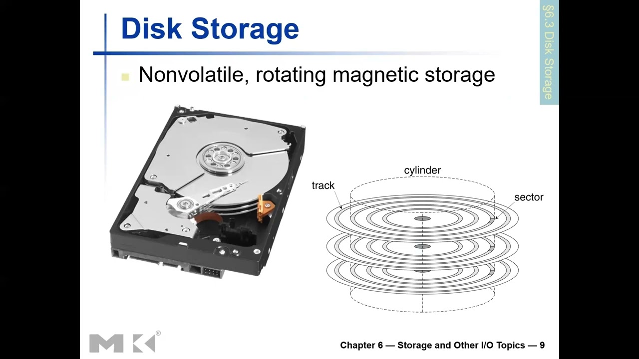
20.11 Magnetic Disk Storage
Traditional secondary storage technology using magnetic recording.
20.11.1 Physical Structure
Disk Shape
- Circular/round shape
- Platter rotates on spindle
Tracks
- Concentric circles on disk surface
- From periphery (outer edge) to center
- Multiple tracks like ribbons arranged concentrically
- Similar to running tracks in sports (Olympics)
Sectors
- Tracks divided by radial lines (from center to periphery)
- Cross-sectional cuts across tracks
- Portion between two separation lines = one sector
- Smallest addressable unit on disk
20.11.2 Sector Contents
- Sector ID (identification)
- Data (512 bytes to 4096 bytes typical)
- Error Correcting Code (ECC)
- Hides defects
- Corrects recording errors
- Gaps between sectors (unused spaces)
20.12 Disk Access Process
20.12.1 Access Components and Timing
1. Queuing Delay
- If other accesses are pending
- Wait for previous operations to complete
- Managed by disk controller
2. Seek Time
- Moving head to correct track
- Head positioned on right sector
- Physical movement of read/write head
- Head placed diagonally on disc
- Time to "seek" the target sector
- Typically several milliseconds
3. Rotational Latency
- Rotating disk to position correct sector under head
- Disk spins to align sector with head
- Choose closest direction (shortest rotation)
- Sectors arranged diagonally on disk
- Multiple sectors per track
- Can rotate either direction (clockwise or counterclockwise)
4. Transfer Time
- Actual data read/write
- Depends on sector size and transfer rate
- Usually small compared to seek and rotation
5. Controller Overhead
- Processing by disk controller
- Command interpretation
- Error checking
- Generally small (fraction of millisecond)
20.12.2 Access Coordination
- Processor initiates access
- Memory Management Unit (MMU) handles translation
- Involves both hardware and operating system
- Reading page from disk to memory: millions of cycles
- Much slower than memory access
20.13 Disk Access Example Calculation
20.13.1 Given Parameters
- Sector size: 512 bytes
- Rotational speed: 15,000 RPM (rotations per minute)
- Seek time: 4 milliseconds
- Transfer rate: 100 MB/s
- Controller overhead: 0.2 milliseconds
- Assume idle disk (no queuing)
20.13.2 Average Read Time Calculation
1. Seek Time
- 4 ms (given)
2. Rotational Latency
- Average = Half rotation time
- Full rotation = 60 seconds / 15,000 RPM = 4 ms
- Average = 4 ms / 2 = 2 ms
- Why half? Can choose closest direction
3. Transfer Time
- Size / Rate = 512 bytes / 100 MB/s
- = 0.005 ms
4. Controller Delay
- 0.2 ms (given)
20.13.3 Total Average Read Time
Total = 4 + 2 + 0.005 + 0.2 = 6.2 milliseconds
20.13.4 Real Case Variation
- Actual average seek time might be 1 ms (not 4 ms)
- Depends on:
- Which sector being accessed
- Current head position
- Distance head must travel
- With 1 ms seek: Total = 3.2 ms
- Significant variation based on access patterns
20.13.5 Additional Examples
- Book provides more practice problems
- Students should try different scenarios
- Understand impact of each component on total time
20.14 Flash Storage
Modern non-volatile semiconductor storage technology.
20.14.1 Characteristics
Advantages
- Non-volatile (retains data without power)
- 1000x faster than magnetic disk
- Smaller physical size
- Lower power consumption
- More robust (no moving parts)
- Can be carried around easily
- Shock resistant
Disadvantages
- More expensive than magnetic disk
- Limited write cycles (wears out over time)
- Technology cost higher
20.15 Types of Flash Storage
20.15.1 NOR Flash
Structure
- Bit cell like NOR gate
- Random read/write access
- Can access individual bytes
Characteristics
- Byte-level access
- Faster read access
- More expensive
Applications
- Instruction memory in embedded systems
- Code storage
- Execute-in-place applications
20.15.2 NAND Flash
Structure
- Bit cell like NAND gate
- Block-at-a-time access
- Cannot access individual bytes directly
Characteristics
- Denser (more storage per area)
- Block-level access
- Reading and writing done in blocks
- Cheaper per GB
Applications
- USB keys/drives
- Media storage (photos, videos)
- Solid-state drives (SSDs)
- Memory cards
20.16 Memory-Mapped I/O
Method of accessing I/O devices using memory addresses.
20.16.1 Concept
- Reserve some address space for I/O devices
- I/O device registers appear as memory locations
- Same address space as memory
- Address decoder distinguishes between memory and I/O
20.16.2 Example with 8 Address Lines
- Total addressable locations: 256 (2^8)
- Reserve 128 locations for memory
- Reserve 128 locations for I/O devices
- Same load/store instructions access both
20.16.3 Access Mechanism
- Use load/store instructions for both memory and I/O
- Operating system controls access
- Uses address translation mechanism
- Can make I/O addresses accessible only to kernel
- Protection mechanism prevents user programs from direct access
20.16.4 Advantages
- Unified programming model
- Same instructions for memory and I/O
- Simpler instruction set
20.16.5 Disadvantages
- Reduces available memory address space
- Must reserve addresses for I/O
20.17 I/O Instructions
Alternative to memory-mapped I/O: separate I/O instructions.
20.17.1 Characteristics
- Separate instructions specifically for I/O operations
- Distinct from load/store (memory) instructions
- Can duplicate addresses:
- Same address can refer to memory location
- Same address can refer to I/O device
- Instruction type determines which is accessed
20.17.2 Access Control
- I/O instructions can only execute in kernel mode
- User programs cannot directly access I/O
- Protection mechanism
- Operating system mediates I/O access
20.17.3 Example Architecture
- x86 (Intel/AMD processors)
- Has special IN and OUT instructions for I/O
- Separate I/O address space
20.17.4 Advantages
- Full memory address space available
- No address space conflict
- Clear distinction between memory and I/O
20.17.5 Disadvantages
- More complex instruction set
- Additional instructions needed
20.18 Polling
Method for processor to communicate with I/O devices.
20.18.1 How Polling Works
1. Periodically Check I/O Status Register
- Processor repeatedly reads device status
- Check if device is ready
- Continuous monitoring in loop
2. If Device Ready
- Perform requested operation
- Read data or write data
- Continue with next task
3. If Error Detected
- Take appropriate action
- Error handling
- Retry or report error
20.18.2 Characteristics
When Used
- Small or low-performance systems
- Real-time embedded systems
- Simple applications
Advantages
Predictable Timing:- Know exactly when device checked
- Deterministic behavior
- Important for real-time systems
- Software handles communication
- No additional hardware needed
- Simple implementation
Disadvantages
Wastes CPU Time:- CPU continuously loops checking device
- Can't do other work while polling
- Inefficient for high-performance systems
- Multiple devices difficult to manage
- CPU time wasted on idle devices
20.18.3 Programming Model
- Can write program to:
- Read status bit from device
- Check if device free
- Make decisions based on status
- Simple control flow
20.19 Interrupts
Alternative to polling: device-initiated communication.
20.19.1 How Interrupts Work
1. Device Initialization
- Device sends signal/request to processor
- Request for service
- Happens when device ready or error occurs
2. Controller Interrupts CPU
- Device controller signals processor
- Processor stops current work
- Handles interrupt
3. Handler Execution
- Special interrupt handler routine runs
- Services device request
- Returns to original program
20.19.2 Characteristics
Asynchronous
- Not synchronized to instruction execution
- Unlike exceptions (which are synchronous)
- Can occur between any two instructions
- Handler invoked between instructions
Fast Identification
- Interrupt often identifies device
- Know which device needs service
- Can be handled quickly
Priority System
- Not all devices have same urgency
- Devices categorized by priority levels
- Devices needing urgent attention get higher priority
- High-priority interrupts can preempt low-priority handlers
20.19.3 Advantages
Efficient CPU Use:- No wasted time polling
- CPU does other work until interrupt
- Each device interrupts when ready
- No continuous checking needed
- Quick response to device events
20.19.4 Disadvantages
More Complex Hardware:- Interrupt controller needed
- Priority management
- Save/restore processor state
- Handler invocation takes time
20.19.5 Execution Model
- Main program running
- Instruction completes
- Interrupt checked
- If interrupt pending:
- Current state saved
- Interrupt handler runs
- State restored
- Resume main program at next instruction
20.20 I/O Data Transfer Methods
Three approaches for transferring data between memory and I/O:
20.21 Polling-Driven I/O
20.21.1 Process
- CPU polls device repeatedly
- When ready, CPU transfers data
- CPU moves data between memory and I/O registers
20.21.2 Issues
- Time consuming
- CPU fully involved in transfer
- Inefficient for high-speed devices
- Wastes CPU cycles
20.22 Interrupt-Driven I/O
20.22.1 Process
- Device interrupts when ready
- CPU services interrupt
- CPU transfers data between memory and I/O registers
20.22.2 Issues
- Still CPU-intensive for data transfer
- CPU must move every byte
- Better than polling but still inefficient for bulk transfers
20.23 Direct Memory Access (DMA)
20.23.1 Process
Setup:- DMA controller handles transfer
- Removes CPU from data movement
- Processor hands off transfer job to DMA controller
- DMA controller transfers data autonomously
20.23.2 DMA Operation
CPU Provides:- Starting address in memory
- Transfer size
- Direction (memory→device or device→memory)
- Transfers data independently
- Operates in parallel with CPU
- No CPU intervention during transfer
- Completion of transfer
- Error occurrence
20.23.3 Advantages
- CPU free to do other work
- Efficient bulk data transfers
- Essential for high-speed devices
- Reduces CPU overhead significantly
20.23.4 When Used
- High-speed devices (disks, network)
- Large data transfers
- When CPU time is valuable
20.23.5 Comparison
- Polling: Simple, predictable, inefficient
- Interrupts: Responsive, better than polling, CPU still involved in transfer
- DMA: Most efficient, essential for high-performance I/O
20.24 RAID (Redundant Array of Independent Disks)
Technology to improve storage performance and dependability.
20.24.1 Purpose
- Improve performance through parallelism
- Improve dependability through redundancy
- Use multiple disks together as single logical unit
20.24.2 Benefits
Performance Improvement
- Parallel access to multiple disks
- Higher throughput
- Faster data access
Dependability Improvement
- Redundancy protects against disk failure
- Data not lost if one disk fails
- Improved reliability
Key Takeaways
- I/O systems connect computers to external devices and storage
- Dependability is critical for storage systems
- MTTF, MTTR, and availability are key metrics
- Magnetic disks use mechanical components with millisecond access times
- Flash storage is faster but more expensive than magnetic storage
- Memory-mapped I/O and separate I/O instructions are two access methods
- Polling is simple but inefficient
- Interrupts improve CPU efficiency
- DMA is essential for high-speed bulk data transfers
- RAID improves both performance and reliability
Summary
This concludes the processor and memory sections of the lecture, covering the complete spectrum from CPU design through memory hierarchy to I/O systems. We have explored how computers are designed from the ground up, from basic arithmetic operations through pipelined execution, memory hierarchies, multiprocessor systems, and finally to storage and I/O mechanisms that enable computers to interact with the external world.