A GUI for control & supervising multiple robots remotely

Team
- E/15/140, Jaliyagoda A.J.N.M., nuwanjaliyagoda@eng.pdn.ac.lk
- E/15/173, Karunarathne S.D.D.D, dinelkadilshani95@gmail.com
- E/15/350, Tennakoon T.M.P.B., pasan96tennakoon@gmail.com
Table of Contents
Introduction
This idea came from a project that is related to swarm intelligence. According to the definition, “Swarm intelligence is the collective behavior of decentralized, self-organized systems” Swarm robotics is applying swarm intelligence to accomplish a bigger task. And it also similar to the behavior of animals like bees, ants, birds, etc.
One of the greatest fallbacks of swarm intelligence-related research is that it is difficult to simulate the algorithms in the real world unless you have a large number of robots to test these algorithms. Building a group of robots takes a lot of time and it is very expensive. As a solution to this problem, we can design or buy general purpose robots which have hardware capabilities to run basic swarm intelligence related algorithms. But buying a set of pre-built robots doesn’t solve the whole problem since it is too expensive yet.
The final goal of this project is not only to design a general-purpose swarm robot unit but designing the simulation platform too. This simulation platform will be able to control basic functionalities of the robots such as assign a robot into a defined place, recharge the robot’s battery when it is draining out, program the robots with giving algorithms, etc… This simulation arena can be accessed from a remote location and these remote users can upload their own algorithms into the robots which are placed in the arena. After upload, they can run it on robots and see the response of the robots using Data and Video feedbacks. Research teams who are working in the field of Swarm Robotics can test their algorithms without taking much effort into hardware. So it saves their time and money.
Introduction Video: youtu.be/40D3IqbQy5A
Solution Architecture
Identifying the scope
Since this whole project is beyond our scope for this unified project we are planning to do only a part of the main project. We hope to create a simulation platform for these robots and control and monitor a few parameters using a remote GUI (Graphical User Interface).
Our goal is to develop a GUI that a user can select robots and specify locations for them in the simulation arena. Then robots will be moved to these specified locations within the smallest possible time by avoiding collisions with other robots.
This project is not only limited to swarm intelligence based problems. We can use what we will develop to increase the efficiency of the real world problems like Search and Rescue Missions, Bomb detection, Planetary exploration, etc. Common facts of these problems are that there is a group or robots which are located in a geographical area and the person who needs controls them from a remote location.
Identifying the requirements
Since we need to remotely monitor and control robots, it is required to establish a communication link between the simulation arena and the end user in real time. This communication link should be able to send and receive messages in both directions
Another requirement is that robots should be able to move into a specified location of the arena. In this case, the robot should be able to identify its current coordinates and the distance of the travel precisely.
When a large number of robots moving in a limited area, there is a high probability to be collisions between robots. We need to find a suitable mechanism to avoid such kind of situations.
We are allowing remote users (through the internet) to control and monitor the robots, so it is compulsory to think about the security of the network.
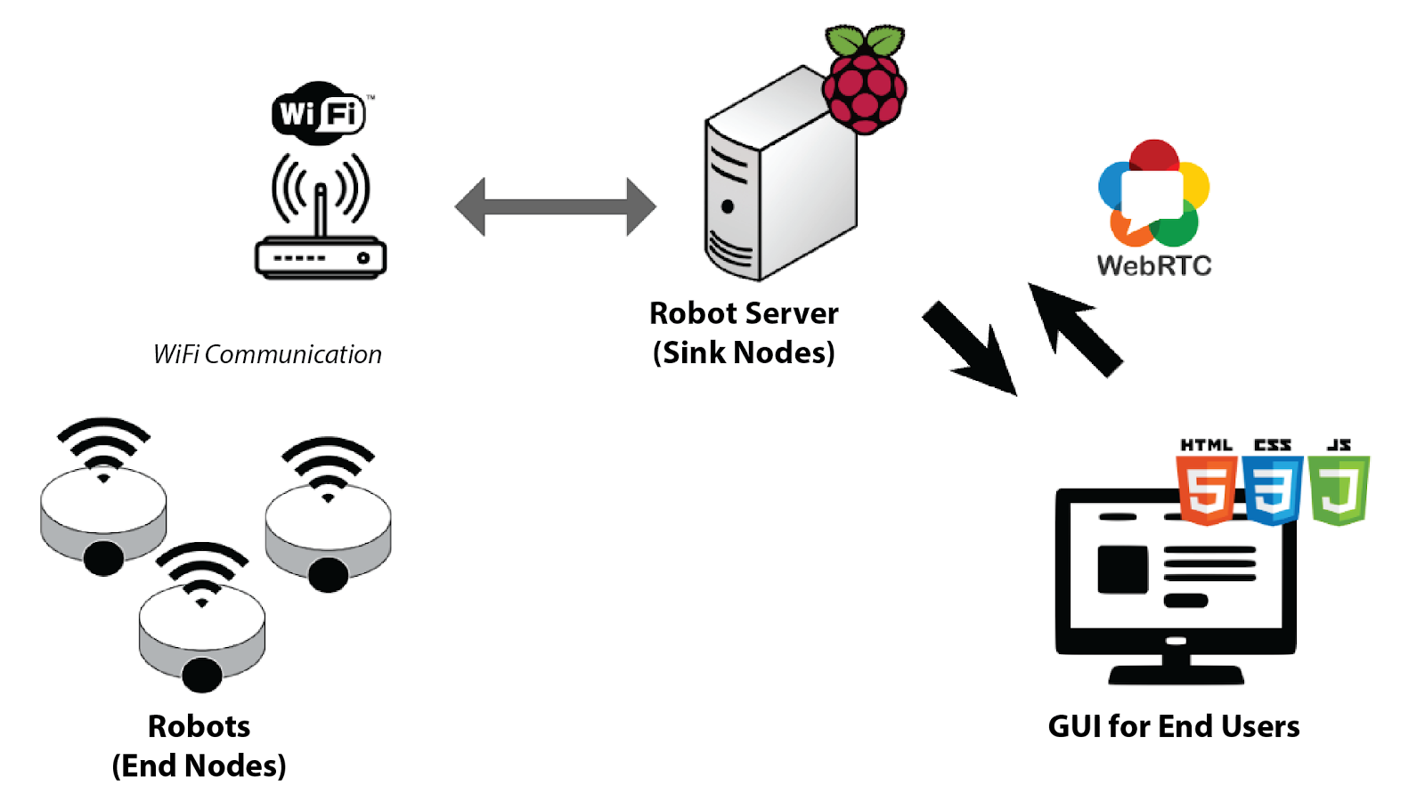
Suggested Data Communication Flow
Hardware and Software Designs
Communication Protocol between Robot Server and End User
When finding a solution for our project, we found a few challenging points. Since we hope to remotely monitor and control ‘multiple’ robots, we wanted to have a real-time communication method between our end nodes (in this case, robots) and the client (in this case, human users) The connection should be able to send control signals from user to robots as well as response messages from the robots.
We first considered RESTful API based server-client architecture, but it was rejected due to it doesn’t support full duplex communication. Next, we looked into use a MQTT Broker between our robots and end user. MQTT (Message Queue Telemetry Transport) was originally developed for low power IoT devices. It is a topic based on communication. Nodes can subscribe to topics, and publish into topics. When a device published data into a topic, MQTT broker will inform it to all the devices/nodes which were subscribed into that topic.

We found another communication protocol known as WebRTC. It is a free and open source project which is developed for communication between browsers and mobile applications in real time. WebRTC is a plugin-free API that most of the modern web browsers support. It has multiple standards and protocols, including STUN/TURN servers, signaling, JSEP, ICE, SIP, SDP, NAT, UDP/TCP, network sockets, and more.
Generally, WebRTC is designed for stream Video and Audio, but there is a channel for data/media stream too. One of our requirements is to remotely monitor the robots and that includes both video and data. So we finally decided to use WebRTC as our communication method.
You can learn more about WebRTC from following links.
Data Communication between Robots and Robot Server
We decided to use WiFi as the default communication method between our robots and the robot server. The main reason to choose WiFi is that we can implement two-way communication for multiple channels with the minimum hardware cost. And can be used in various communication protocols, which are developed on top of the basic WiFi protocols such as IEEE 802.11
Robot Navigation Control
Since our robots will be controlled remotely, robots should be able to handle incoming commands while navigating. Due to the practical hardware problems, robots can’t move on straight directions and take precise turns without feedback loop based control structures. Most of the available sensors that measure the distance have errors and when we continually taking measurements, it will add cumulative errors. So we decided to avoid this by doing a small modification to our platform.
We decided to use a black color grid on the arena, so robots can follow the lines and correct the cumulating errors from the junctions when it is passing them. Not only that, it can use this grid system to take 90 degree turns using floor color sensors and a simple feedback loop.

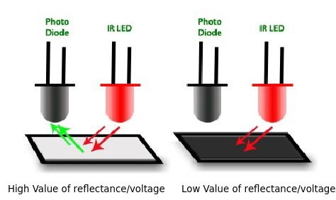
To identify the black lines from the white background, we decided to use IR Transmitter Receiver pairs. Principle of this sensor is that white color background reflects the IR beam emitted by the IR diode, but not by the black color background. The voltage output of the Photodiode will depend on the amount of reflection. Currently, we hope to feed this digital signal into our microcontroller as an external hardware interrupt, rather than polling digital inputs. So we decided to use an Op-amp circuit with Voltage comparator arrangement to convert this analog reading into a digital signal.
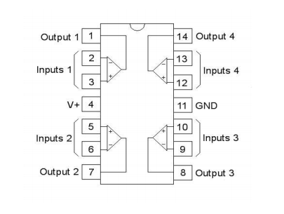
The comparator is an electronic decision-making circuit that makes use of an operational amplifier very high gain in its open-loop state, that is, there is no feedback resistor. The Op-amp comparator compares one analog voltage level with another analog voltage level, or some preset reference voltage, VREF and produces an output signal based on this voltage comparison. In other words, the op-amp voltage comparator compares the magnitudes of two voltage inputs and determines which is the largest of the two.

We have designed the comparator circuit using the IC named, LM324. The operational amplifier LM324 IC can work like a normal comparator, and it comprises four independent op-amps internally. This IC has designed with low-power, bandwidth and high stability for operating with single power supply over extensive voltage ranges. The range of operating voltages of this IC includes 3.0 V for low and 32 V for high. The range of common mode input mainly comprises the negative voltage supply, thus removing the requirement of outside biasing components in several applications. The range of output voltage also comprises the negative voltage supply.
Voltage Reference for the comparator circuit is provided by a Multi-turn trimming resistor because it can be configured as a voltage divider more precisely than a usual Preset Resistor.
Here are the Schematic Diagram and the PCB layout of the comparator circuit we have designed. We used an open-source software called Fritzing to design the PCB. Circuit board was fabricated using the PCB milling method, which engraves and isolate the circuit paths on copper plate.
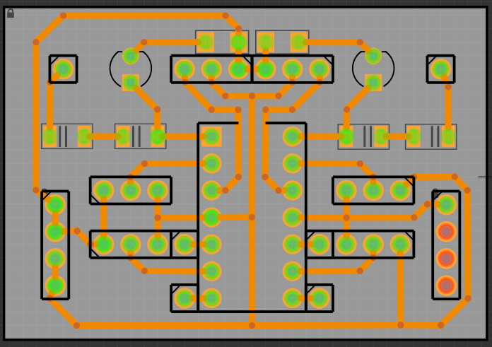
Overview of the PCB Design
To design the PCB, we used free and open-source software named Fritzing. The PCB is a single layer design and we used jumper cables to avoid crossed signal paths. To fabricate the PCB, the design was exported as a Gerber file and processed with the software named dipTrace.
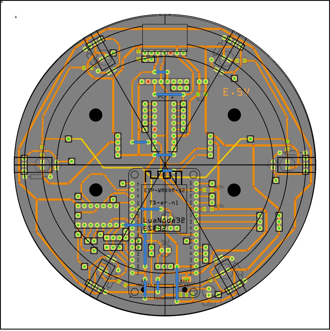
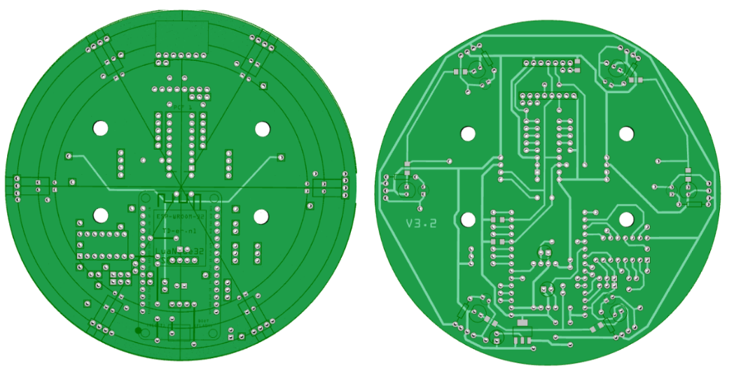
After processing the Gerber file, it was imported into a software named, FlatCAM to convert the PCB design into a toolpath for machinery. The G-Code files which exported from the FlatCam were sent to the CNC milling machine, and the machine fabricated the PCB by few isolating milling and drilling cycles.
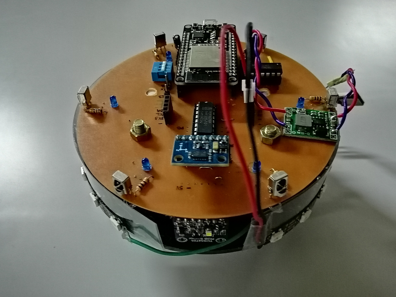
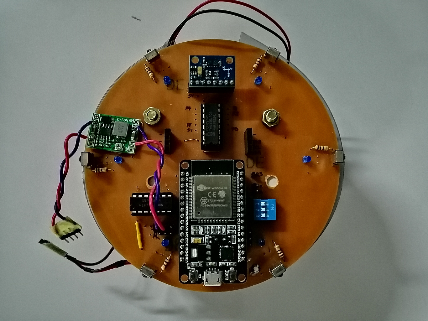
After two and a half hours of soldering, we were able to completely assemble the PCB as shown below. (We used a ready-made power supply known as a DC to DC Buck converter to reduce the battery voltage of 8.4v to 5v and it is the green color module you can see in below image)
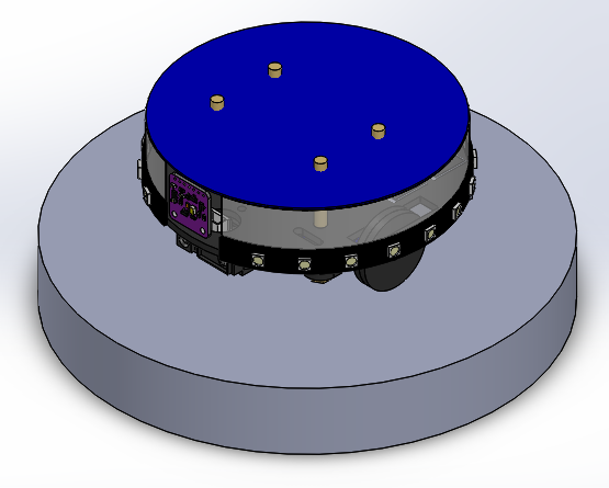
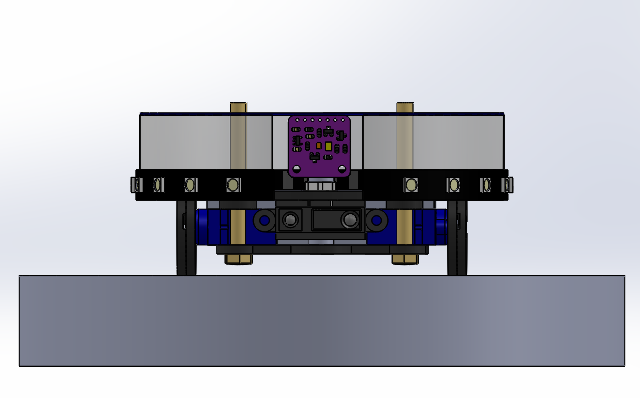
Overview of the Robot Design
We have used SolidWorks for designing the structure of the robot. After a few design revisions, we came up with the following design. We decided to use a round shape for the robot.
We used a black 3mm Cladding Board as the raw material of the base. The design was fabricated by CNC milling, using a 1.5mm end milling bit with a contour milling operation. Wheels also manufactured using the same material and using the same method.
We used 5mm x 60mm Hex bolts, M5 nuts, and M5 washers as the spacers between two base plates and the PCB layer.