INTRODUCTION
“Poultry Master” is a mobile application incorporated with a automated poultry feeding system which helps the farmers to handle the feeding of the farm efficiently. Due to the high labor demand and labor cost, farmers are facing difficulties in monitoring and feeding the poultry farm in order to get high output from the farm. Poultry master help to overcome the all the difficulties in feeding and monitoring the feeding behavior.
Problems in feeding manually
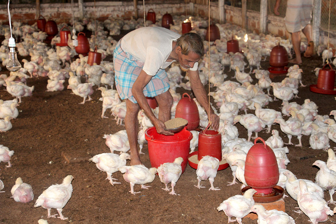
There are many problems faced by a poultry farmer when feeding manually. Some of the most prominent problems are identified below,
- High labor demand and cost
- Time consuming process
- Spread of diseases
- Increase in mortality
Automated feeding approach
To over come the above mention problems faced by the farmer, the following most promising solutions are being stated below,
- Adequate number of labors
- Saving cost for labors
- Safe, convenient and reaction of the chicken is small
- Feed and water regulation
Solution Architecture
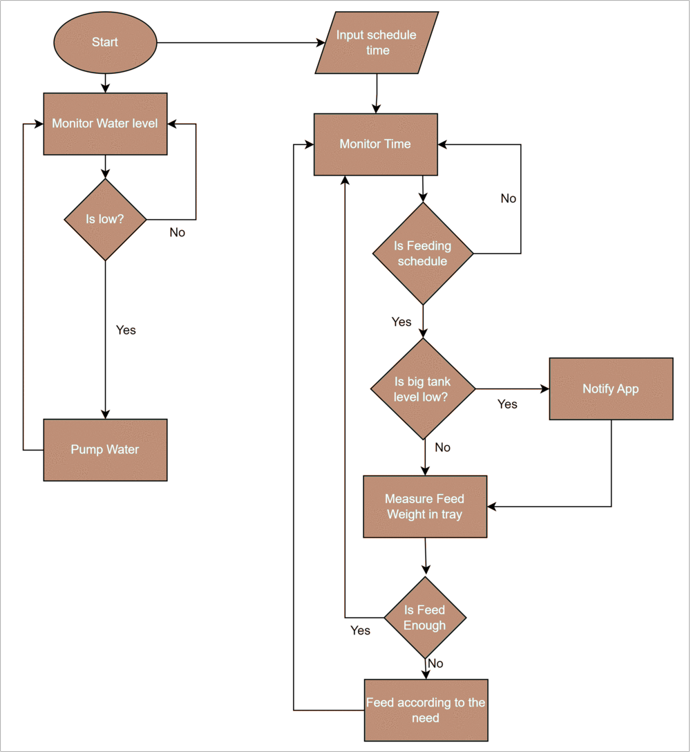
This flowchart represents the solution architecture of our system. The user must schedule a time for feeding using the mobile app and once the scheduled time is reached, our system checks feed level in the main feed tank. If the feed level is less than the minimum required feed level, then our system will notify the farmer through the mobile app to remind him about refilling the tank. If the feed level is greater than the minimum required feed level, then the system will measure the feed weight in the small feeders, and according to the balance feed amount, system will provide feed according to the need. This process happens on a loop automatically.
In the watering part of the system, once the sensor reading is less than the minimum level, then our system triggers the water supply valve to to provide water to the liquid feeders. This process happens on a loop without a scheduled time.
Data and control flow
This is a high level view of our system. Here all the sensors and actuators are connected with NodeMCU. The sensors sends data to the NodeMCU and the actuators get the control signal from the NodeMCU according to the sensor datas and it starts to work. The data flows to the database through the wifi module via wifi connection. The main role of backend is to connect the hardware front end with the software front end which is a mobile application here.
Hardware Implementation
Hardware components
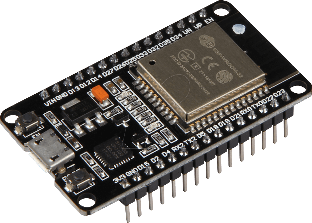
ESP32 DevKit v1
The Esp32 DevKit v1 is one of the development board created to evaluate the ESP-WROOM-32 module. It is based on the ESP32 microcontroller that boasts Wifi, Bluetooth, Ethernet and Low Power support all in a single chip.
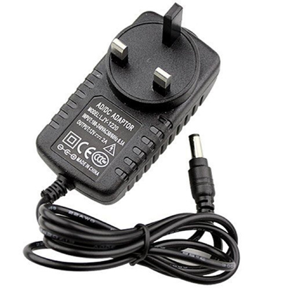
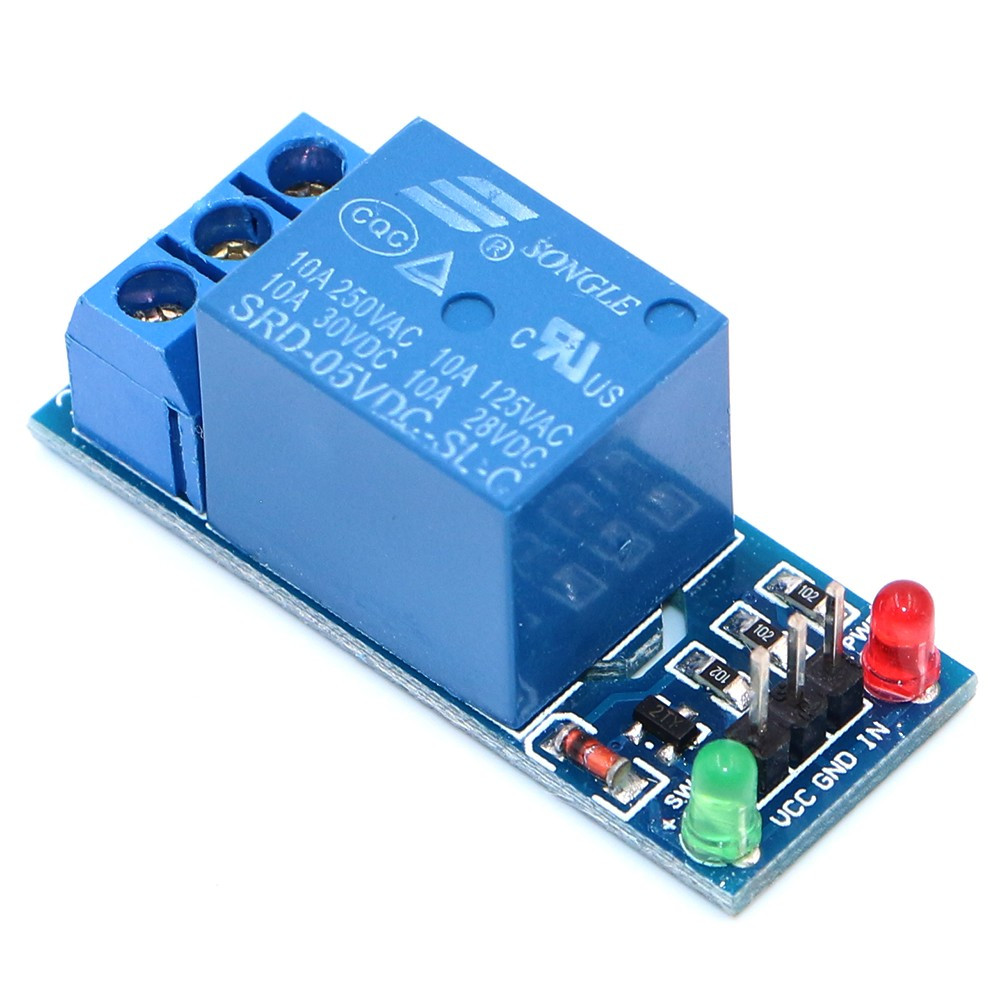
12V Power Adapter
A DC power supply 12V is an electronic circuit that converts an AC voltage to DC voltage. Here which is use to supply voltage to solenoid valve.
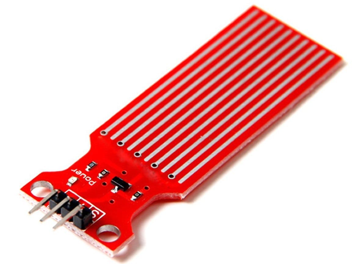
Water Level Sensor
Water level sensors detect the level of liquids and other fluids and fluidized solids
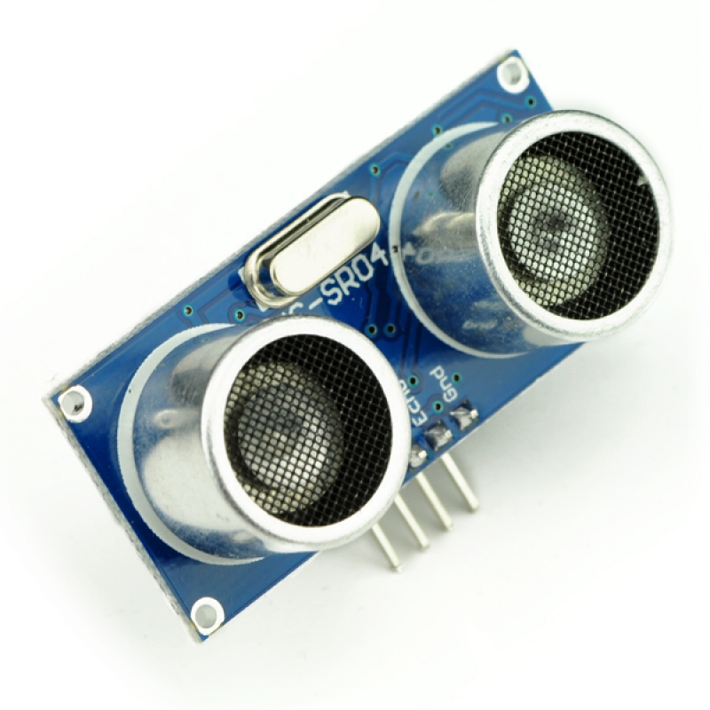
Ultra Sonic Sensor
An ultrasonic sensor is an electronic device that measures the distance of a target object by emitting ultrasonic sound waves, and converts the reflected sound into an electrical signal.
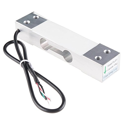
Load Cell Sensor
A load cell (or loadcell) is a transducer which converts force into a measurable electrical output.
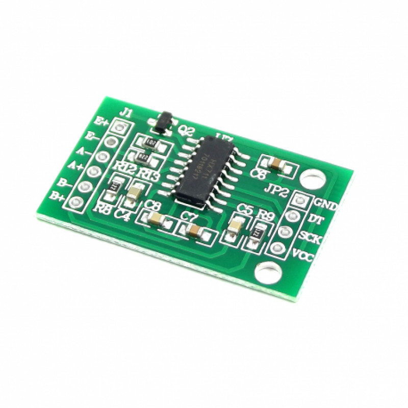
HX711 Amplifier
The HX711 amplifier is a breakout board that allows you to easily read load cells to measure weight.
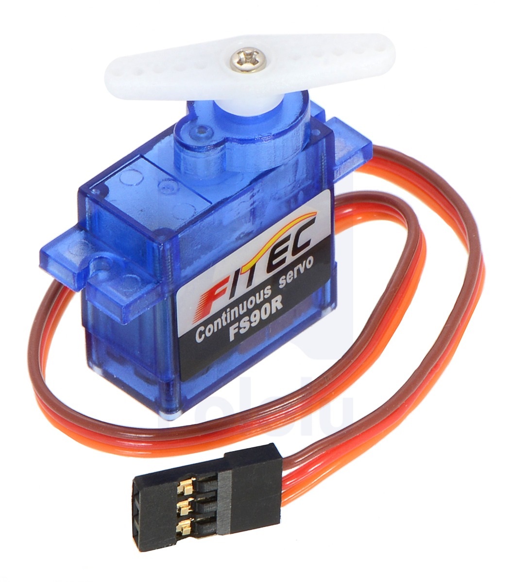
Servo Motor
A servomotor (or servo motor) is a rotary actuator or linear actuator that allows for precise control of angular or linear position, velocity and acceleration.
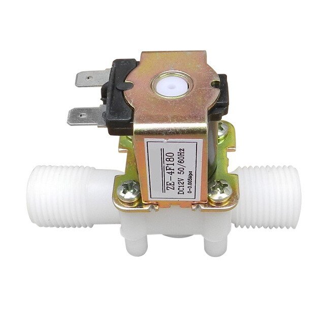
Solenoid Valve
Solenoid valves are the most frequently used control elements in fluidics. Their tasks are to shut off, release, dose, distribute or mix fluids.
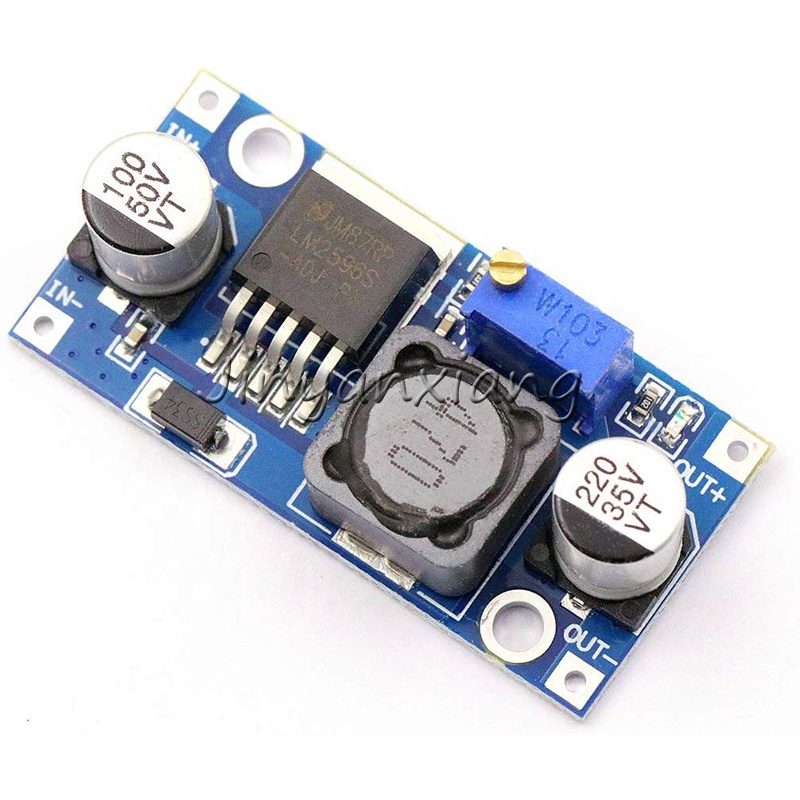
DC to DC stepdown converter
This DC-DC 12V to 3.3V 5V 12V Power Module Multi Output Voltage Conversion is also known as Buck Converter or also as Step-Down Voltage Converter. The module is capable of altering the output of the power source/supply before supplying it to the load so as to deliver the specified power to your load.
Product Design
3D Model
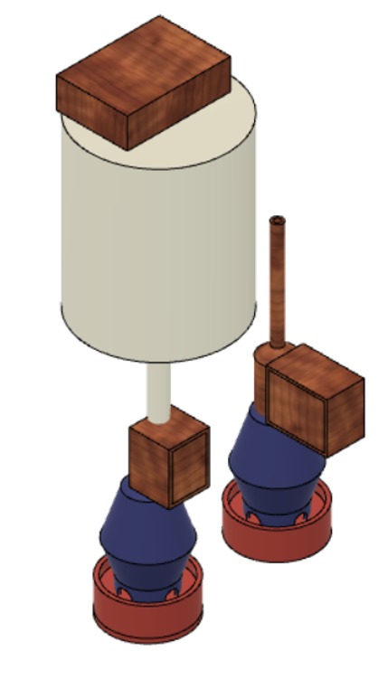
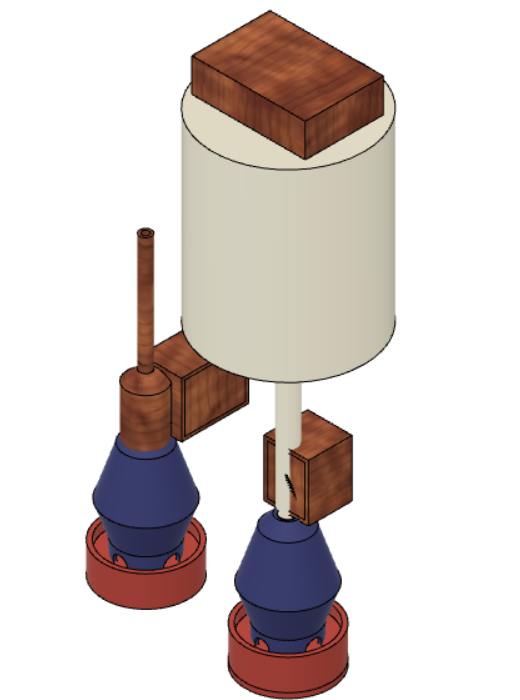
The above 3D modal describes the basic shape proposed to facilitate the feed and water flow and control of the hardware system. The chick feeder has a hollow region opening up through a narrow hole to a narrow tray reducing the wastage of feed and prevenng the exposure of the tray so that the chicks would waste the feed. The feeder is connected through a solenoid valve to a overhead tank which has a funnel shaped connector between the feeder pipe coming out of the solenoid valve and the overhead tank. This facilitates the smooth flow of feed and prevents the feed from retaining in any part of the tank or pipes. Water path has similar shape where we have a overhead tank in absence of a funnel opening.
Our Designed Prototype
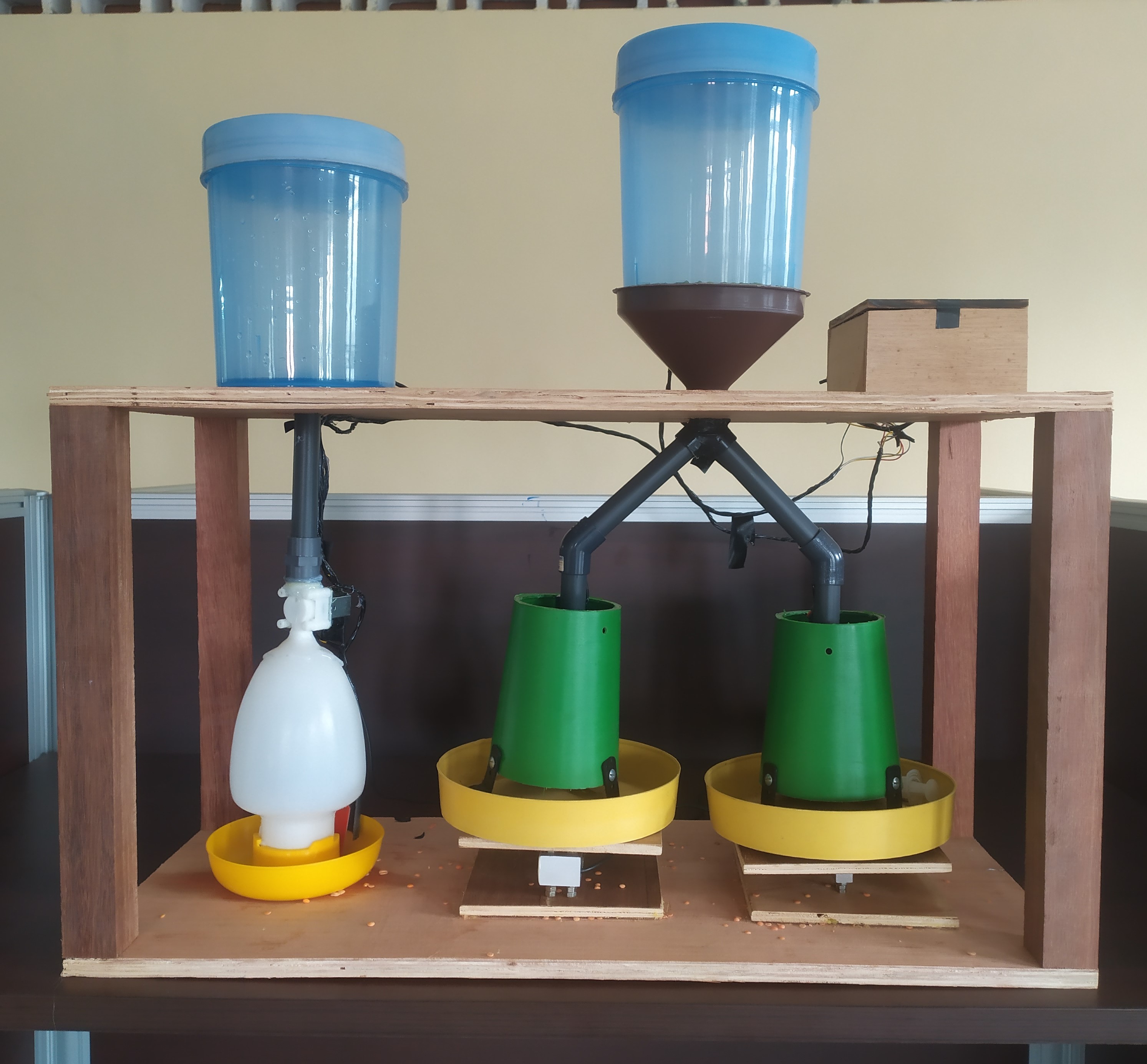
Automated feeding system
This product mainly focuses the small scale farmers who maintains a open farm concept
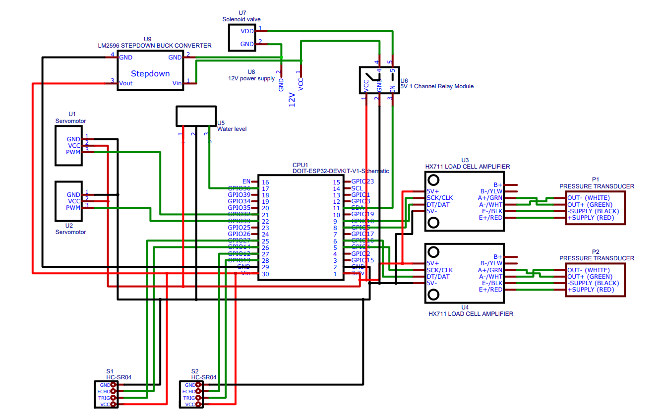
HomeCircuit Diagram
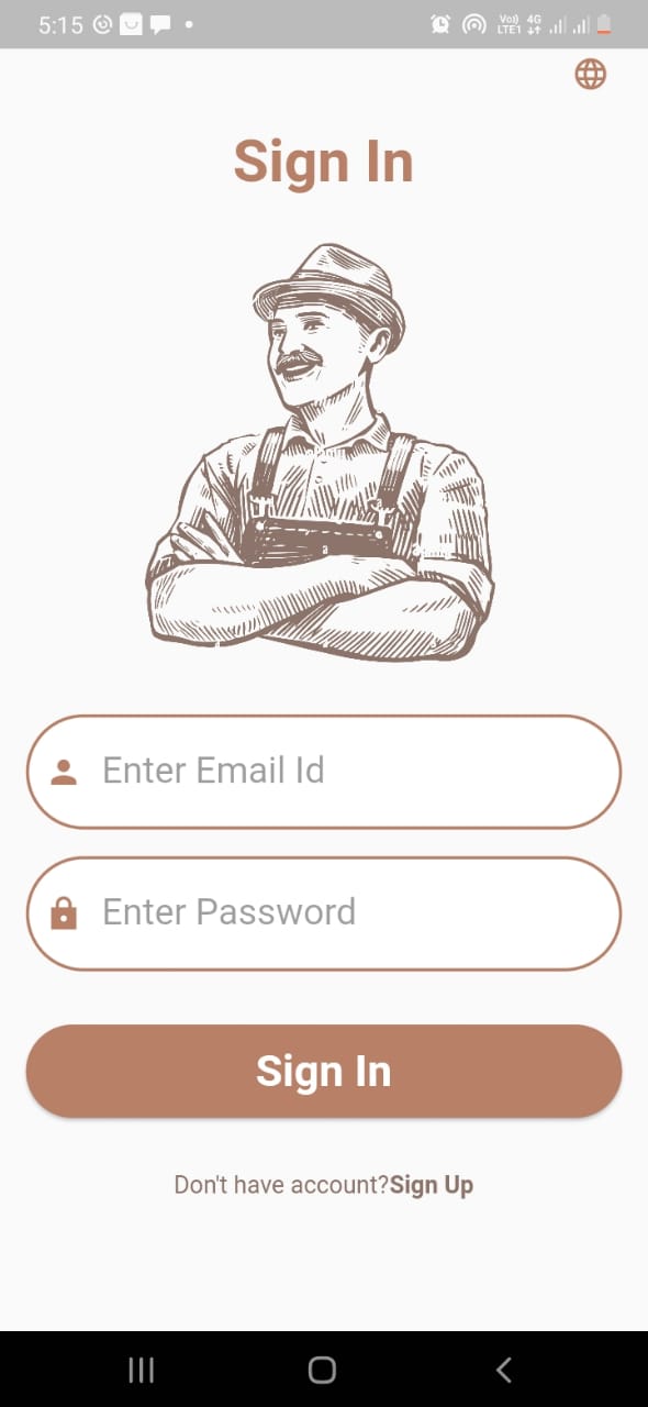
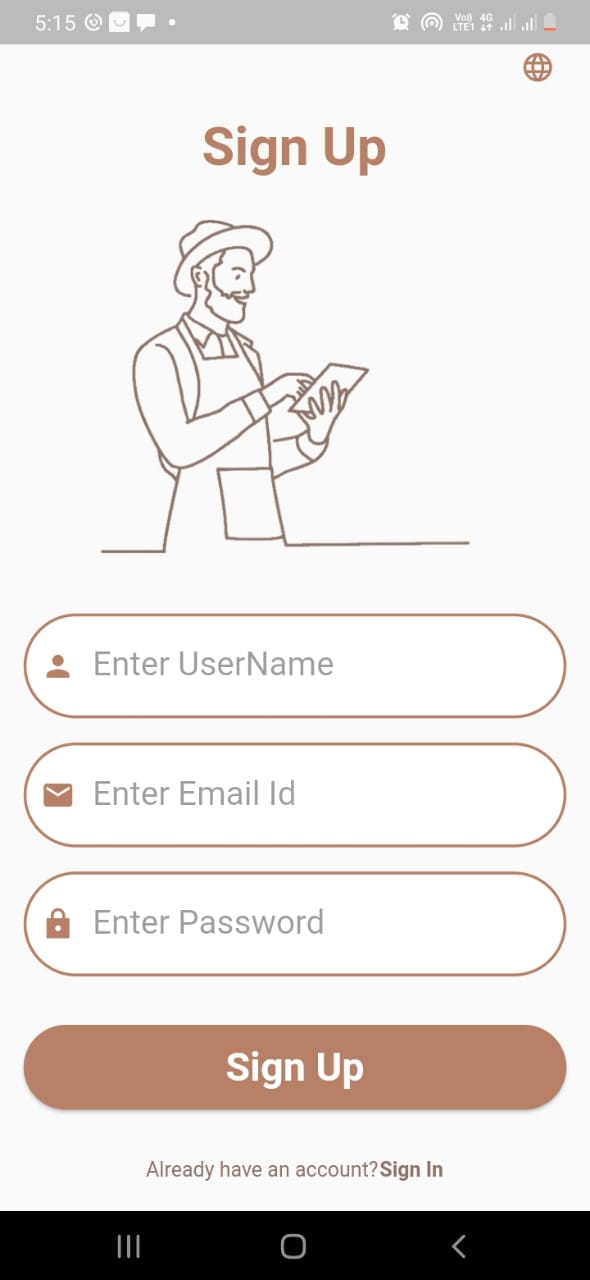
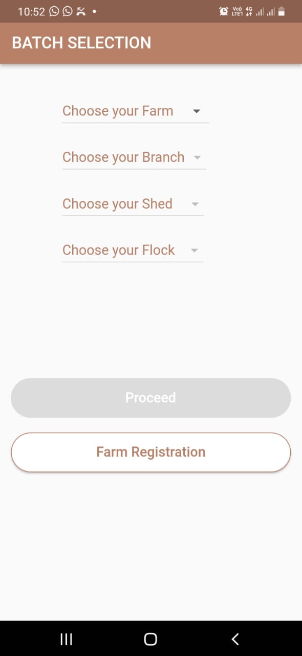
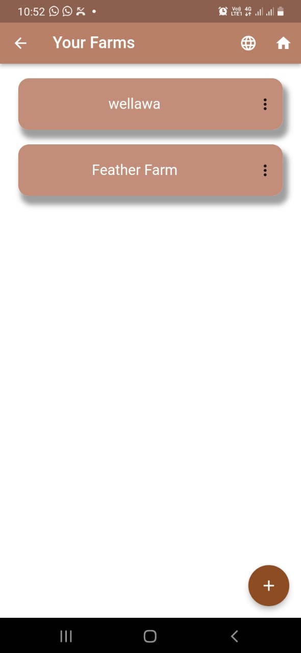
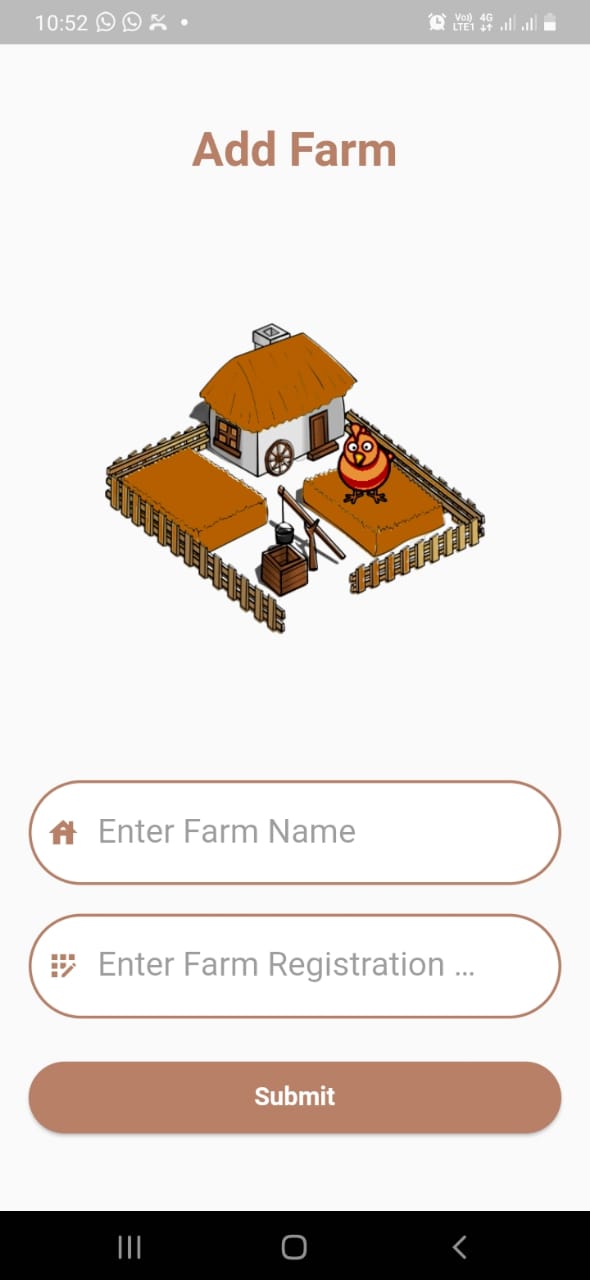
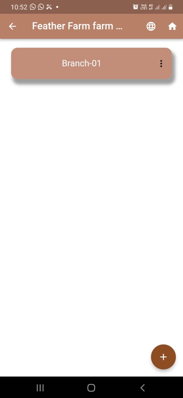
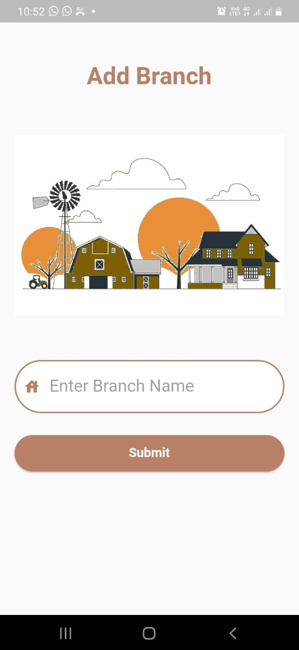
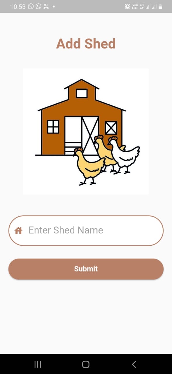
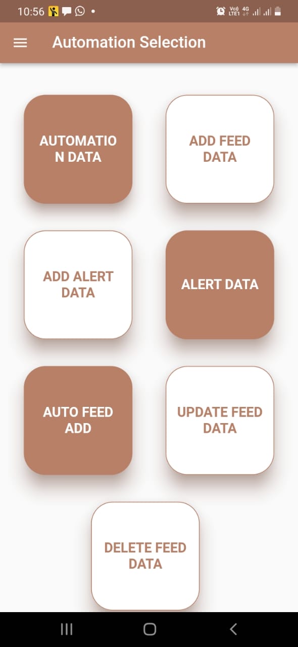
UI Design
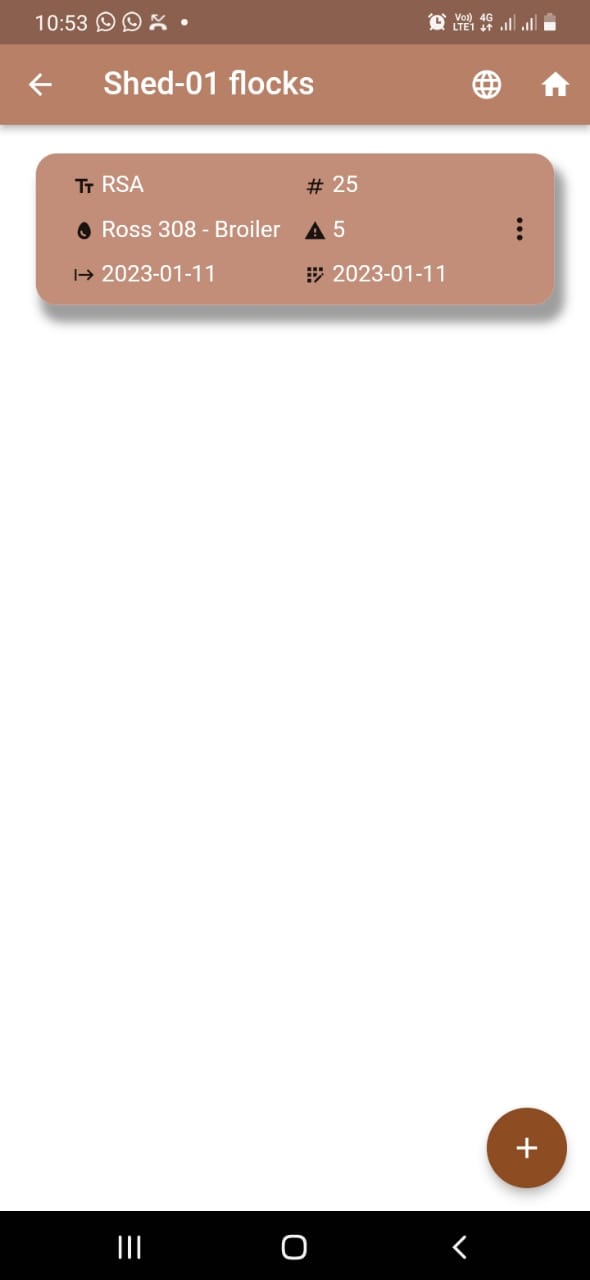
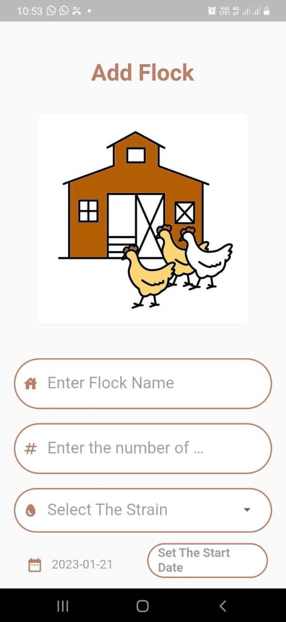
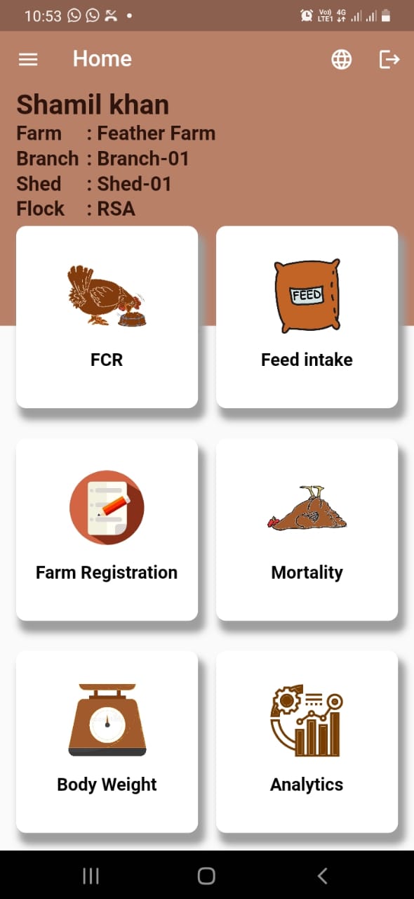
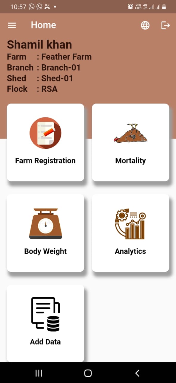
Mobile Application


Database
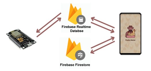
We have used firebase real-time database and the fire store to store and retrieve data from the sensors. The main role of the database is to connect the hardware front end with the software frontend which is a mobile application in our case.
The hardware system is connected with the real time database of the firebase The mobile Application in connected with the firebase fire store database The connection between the real-time database and the fire store database is established in order to connect both the hardware node and the mobile application.
Demonstration
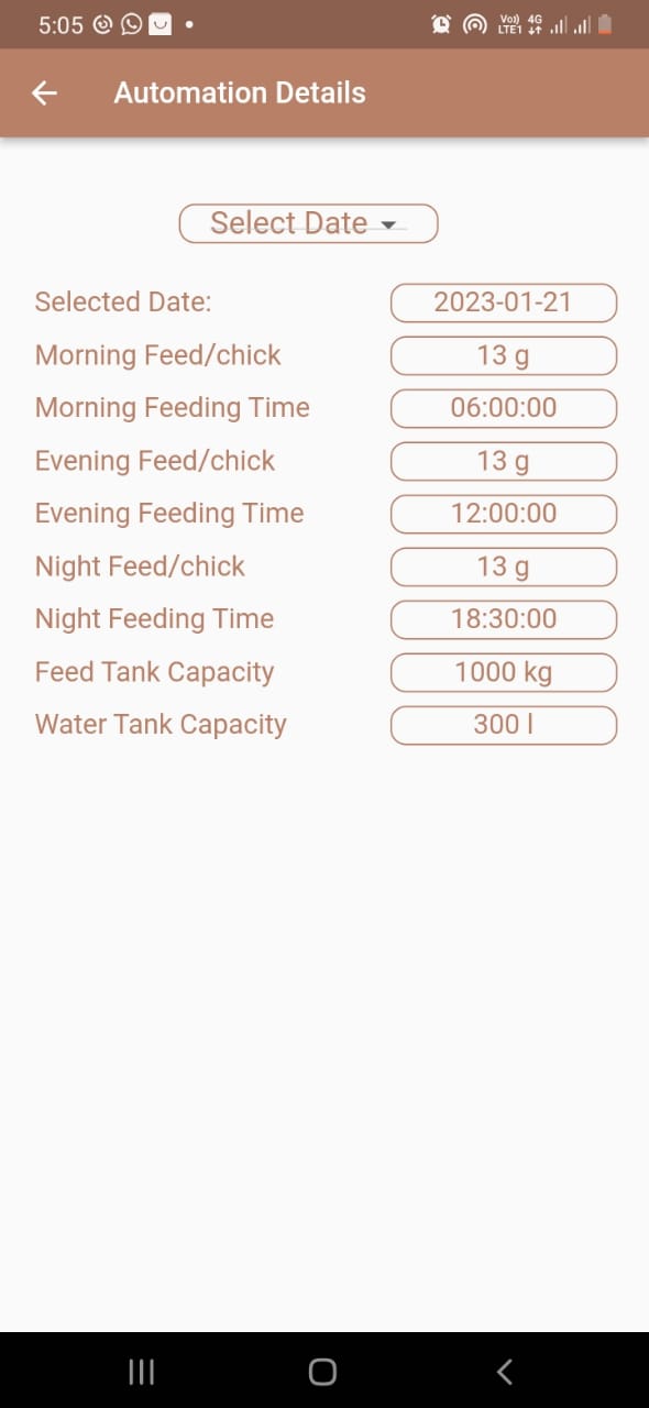
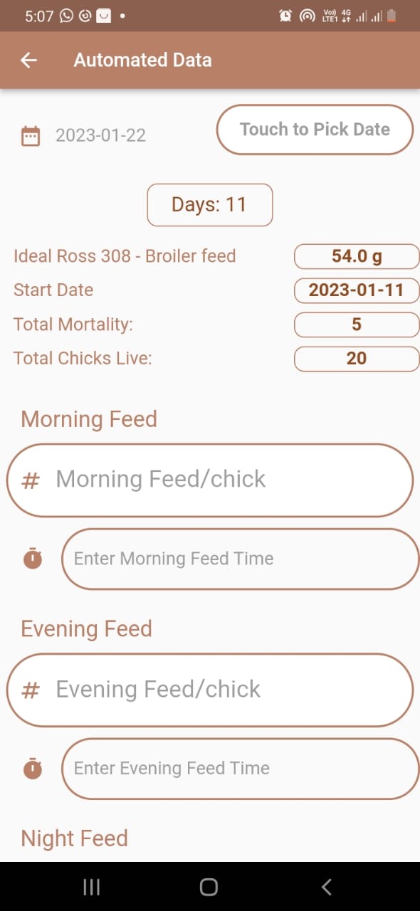
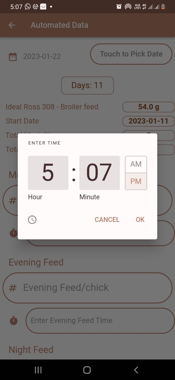
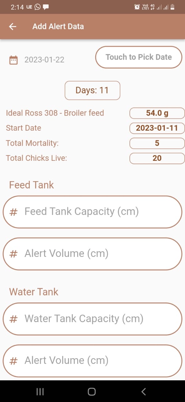
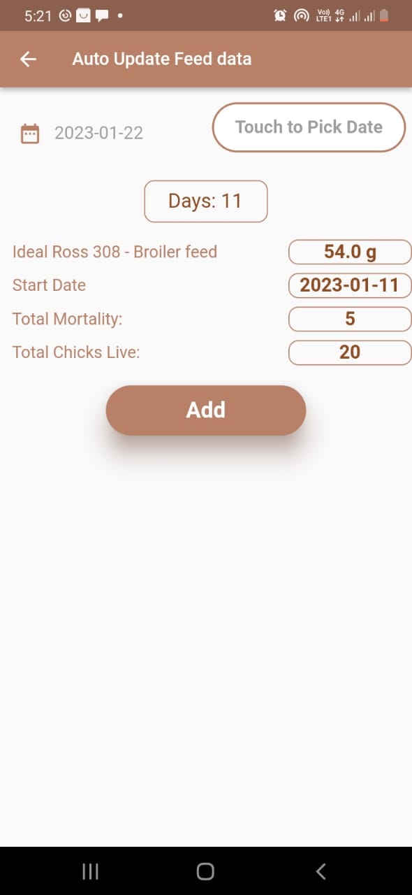
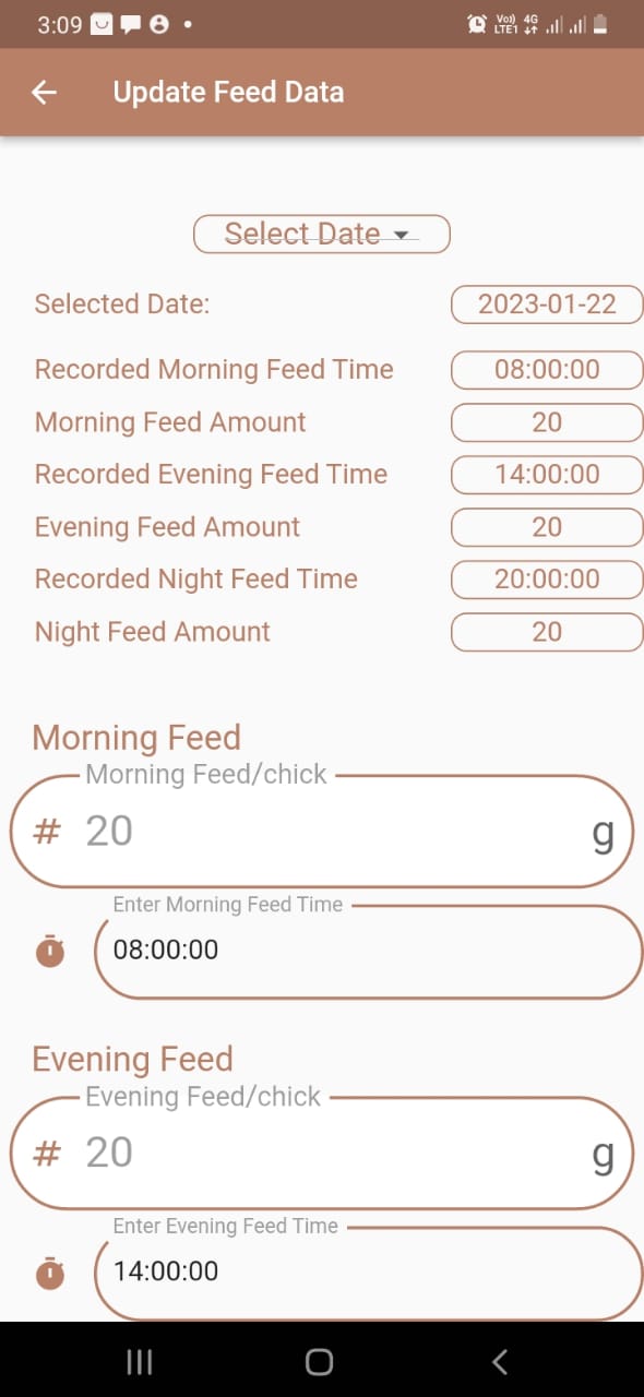
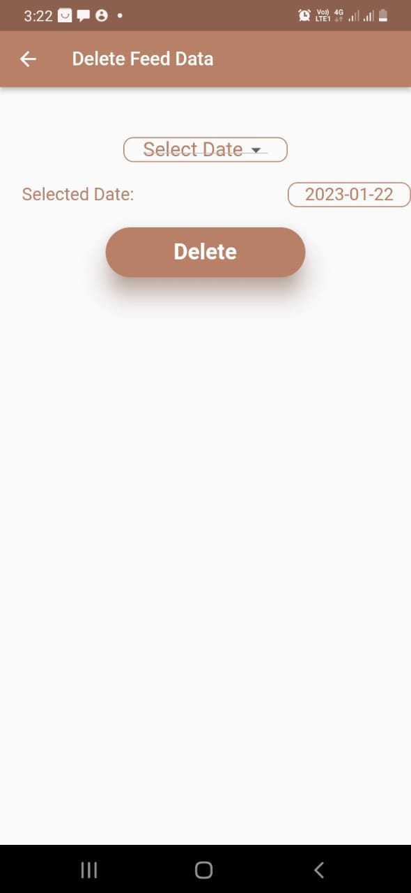
scheduling Feed time and Feed amount
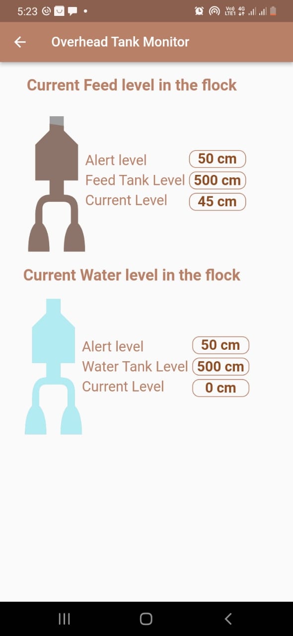
Overhead Tank Feed and Water level monitoring
Testing
Software Test
Responsive Test
Robo Test
Widget Test
Hardware Test
- Each hardware node was tested individually in order to ensure the working condition of each sensor.
- Connecting the Realtime database using the inbuilt Wi-Fi in the esp32 and tested the data flow from both ends. Based on the movement in the ultrasonic sensor the device sends the appropriate sensor values to the Realtime database.
Refer the testing videos using the given link
Click me to watch Test video - Different time were scheduled and tested whether the servo motor opens at the correct time.
Database
- Manual testing was carried out by changing the sensor positions and observed the change in the database. Updated values using the mobile application and observed the change in database values.
- Used Firebase analytics to test the backend of the system.
Team
Our Team

Aarah J.F.
UndergraduateComputer Engineer
Faculty of Engineering
University of Peradeniya

Khan A.K.M.S.
UndergraduateComputer Engineer
Faculty of Engineering
University of Peradeniya

Rishad N.M.
UndergraduateComputer Engineer
Faculty of Engineering
University of Peradeniya
OUR SUPERVISERS

Dr. Isuru Nawinne