Click the thumbnail above to watch the video lecture on YouTube
17.1 Introduction
This lecture explores cache hierarchies in modern computer systems, examining how multiple levels of cache work together to optimize memory access performance through careful balance of hit latency versus hit rate. We analyze real-world implementations including Intel's Skylake architecture, understanding the design decisions behind multi-level cache organizations where L1 caches prioritize speed, L2 caches balance capacity and latency, and L3 caches provide large shared storage across processor cores. The examination of associativity tradeoffs—from direct-mapped through set-associative to fully associative designs—reveals how hardware complexity, power consumption, and performance interact in practical cache systems.
17.2 Recap: Associativity Comparison Results
From the previous lecture's example using a 4-block cache with three different organizations:
17.2.1 Direct Mapped Cache
- Result: 5 misses, 0 hits
- Cold misses: 3 (compulsory, unavoidable)
- Conflict misses: 2 (data evicted then accessed again)
- Utilization: Poor - only 2 of 4 slots used
- Hit rate: 0% in this example
17.2.2 2-Way Set Associative Cache
- Result: 4 misses, 1 hit
- Cold misses: 3
- Conflict misses: 1
- Utilization: 2 of 4 slots used
- Hit rate: 20% - better than direct mapped
17.2.3 Fully Associative Cache (4-way)
- Result: 3 misses, 2 hits
- Cold misses: 3 (only unavoidable misses)
- Conflict misses: 0
- Utilization: Best - 3 of 4 slots used
- Hit rate: 40% - best performance
17.2.4 Key Observations
- Higher associativity → better hit rate
- Higher associativity → reduced conflict misses
- Cold misses occur at program start and when new addresses are accessed
- System reaches "steady state" with mostly conflict misses after initial cold misses
- Performance improvement comes at cost of complexity and power
17.3 Cache Configuration Parameters
17.3.1 Primary Parameters
1. Block Size
- Size of a single block in bytes
- Cache deals with memory in blocks
- CPU deals with cache in words/bytes
2. Set Size
- Number of sets in the cache
- Direct mapped: number of sets = number of entries
- Fully associative: only 1 set
- Can be confusing - refers to number of sets, not size of each set
3. Associativity
- Number of ways in a set
- Number of blocks that can be stored in one set
- 1-way = direct mapped
- 2-way = two-way set associative
- N-way = N blocks per set
17.3.2 Cache Size Calculation
Total Cache Size = Block Size × Set Size × Associativity
17.3.3 Secondary Parameters
4. Replacement Policy
- LRU (Least Recently Used)
- Pseudo-LRU (PLRU)
- FIFO (First In First Out)
- Others
5. Write Policy
- Write-through
- Write-back
6. Other Optimization Techniques
- Prefetching mechanisms
- Write buffer size
- Communication protocols
17.3.4 Configuration Definition
- Fixing values for all these parameters defines a specific cache configuration
- Performance and power consumption are determined by configuration
- External factors: memory access patterns from CPU/program
17.4 Improving Cache Performance
17.4.1 Average Access Time Equation
T_avg = Hit Latency + Miss Rate × Miss Penalty
Three main factors can be optimized as below.
17.5 Hit Rate Improvement
17.5.1 Method 1: Increase Cache Size
Approach:- Most obvious and intuitive method
- More slots → can hold more data → more likely to get hits
- Very expensive (SRAM costs ~$2000/GB)
- SRAM uses cutting-edge technology, same as CPU
- Must be fast enough to work at CPU speed
- Usually located inside CPU core
- Practical limit on how much cache can be added
17.5.2 Method 2: Increase Associativity
Benefits:- Higher associativity → better hit rate
- Reduces conflict misses
- Most popular technique for given cache size
- Increases hit latency
- Increases power consumption
- Increases hardware cost
17.5.3 Method 3: Cache Prefetching
Concept:- Fetch data before it's needed
- Similar to branch prediction in CPU
- Reduces cold misses (compulsory misses)
- Can also reduce conflict misses
- Software prefetching (compiler-based)
- Hardware prefetching
- Hybrid software-hardware approaches
- Can predict and fetch data before CPU requests it
- Reduces effective miss rate
- Can significantly improve performance for predictable access patterns
- Not 100% accurate
- Wrong predictions waste power and bandwidth
- Requires additional hardware
- Increases complexity
17.6 Hit Latency Optimization
17.6.1 Relationship with Hit Rate
Fundamental Trade-off:- Hit rate and hit latency are tied together
- Improving hit rate often increases hit latency
- Improving hit latency often reduces hit rate
- Need to find optimal balance
- Higher associativity → better hit rate BUT higher hit latency
- Smaller, simpler cache → lower hit latency BUT worse hit rate
- Must balance these competing factors
- Depends on application requirements
- Different trade-offs for different use cases
17.7 Miss Penalty Improvement
17.7.1 Miss Penalty Definition
- Time spent servicing a cache miss
- Time to fetch missing block from memory
17.7.2 Method 1: Optimize Communication
- Improve bus technology between cache and memory
- Increase bus width
- Increase bus speed
- Optimize bus arbitration
- Better communication protocols
- This assumes best possible communication is already in place
17.7.3 Method 2: Cache Hierarchy (Main Focus)
- Use multiple levels of cache
- Each level optimized differently
- Most effective technique for reducing miss penalty
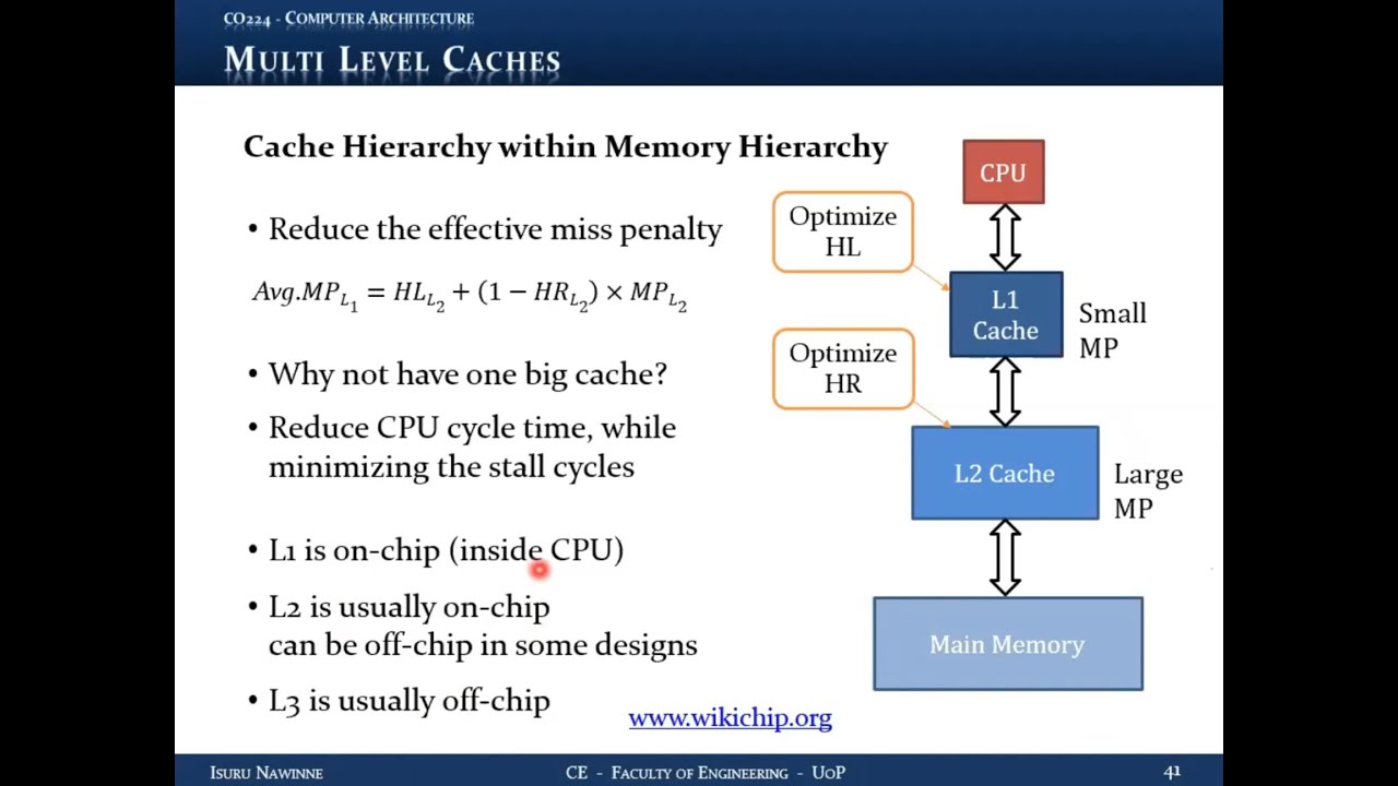
17.8 Cache Hierarchy (Multi-Level Caches)
17.8.1 Concept
Instead of a single cache between CPU and memory, use multiple cache levels: L1, L2, L3, etc., with each level serving as backup for the level above.
17.8.2 Terminology
- L1 (Level 1): Top-level cache, closest to CPU
- L2 (Level 2): Second-level cache
- L3 (Level 3): Third-level cache (in some systems)
- Top-level cache: Fastest, smallest
- Last-level cache: Slowest (but still fast), largest
17.8.3 Operation
- CPU requests data from L1
- L1 miss → request goes to L2 (not directly to memory)
- L2 miss → request goes to L3 (if exists)
- Last-level miss → request goes to main memory
17.8.4 Benefits
- Reduced effective miss penalty for L1
- Most L1 misses served by L2 in few cycles (2-4 cycles)
- Only L2 misses incur full memory penalty (100+ cycles)
- Overall average miss penalty greatly reduced
17.8.5 Effective Miss Penalty
For L1 cache:
Effective Miss Penalty = L2 Hit Latency + L2 Miss Rate × L2 Miss Penalty
If L2 has good hit rate:
- L2 miss rate is low
- Most L1 misses served quickly by L2
- Effective penalty much less than going to memory
17.8.6 Example Calculation
Given:
- L1 miss rate: 5%
- L2 hit rate: 99.9%
- L2 hit latency: 3 cycles
- Memory penalty: 100 cycles
L1 effective penalty = 3 + 0.001 × 100 = 3.1 cycles
17.9 Optimization Strategies for Multi-Level Caches
17.9.1 Why Not One Big Cache?
- Different levels can be optimized for different goals
- Splitting allows specialized optimization
- Better overall performance than single large cache
17.10 L1 Cache Optimization - Optimize for Hit Latency
17.10.1 Goal
Minimize hit latency
17.10.2 Rationale
- Critical for CPU clock cycle time
- Memory access is slowest pipeline stage
- Determines overall CPU clock period
- Lower L1 hit latency → shorter clock cycle → higher CPU frequency
17.10.3 Characteristics
- Small size
- Lower associativity (2-way, 4-way, sometimes 8-way)
- Fast response time
- Accept moderate hit rate (e.g., 95%)
17.10.4 Trade-off
- Sacrifice some hit rate for speed
- Slightly higher miss rate acceptable
- Misses handled by L2
17.11 L2 Cache Optimization - Optimize for Hit Rate
17.11.1 Goal
Maximize hit rate
17.11.2 Rationale
- Serve most L1 misses
- Minimize accesses to main memory
- Reduce effective L1 miss penalty
17.11.3 Characteristics
- Larger size
- Higher associativity (8-way, 16-way, or even fully associative)
- Very high hit rate (99.9% or better)
- Can tolerate higher hit latency
17.11.4 Trade-off
- Higher latency acceptable
- Not on critical path for most accesses
- Priority is catching L1 misses
17.12 Associativity Comparison
Question: Which level has higher associativity? Answer: L2 (and L3 if present) have higher associativity17.12.1 Reasoning
- L2 optimized for hit rate
- Higher associativity → better hit rate
- L1 optimized for latency
- Lower associativity → faster access
17.12.2 Combined Effect
- L1: Fast but moderate hit rate (e.g., 95-98%)
- L2: Slower but excellent hit rate (e.g., 99-99.9%)
- Most accesses: L1 hit (fast path)
- Most L1 misses: L2 hit (medium path, few cycles)
- Very few accesses: Main memory (slow path, 100+ cycles)
17.13 Physical Implementation of Cache Hierarchy
17.13.1 L1 Cache
- Almost always on-chip (inside CPU die)
- Integrated within CPU core
- Smallest but fastest
- Typically split into:
- L1 instruction cache (L1-I)
- L1 data cache (L1-D)
17.13.2 L2 Cache
- Usually on-chip (same die as CPU)
- Can be off-chip in some designs
- Larger than L1
- May be unified (instruction + data) or split
- If multi-core: may be per-core or shared
17.13.3 L3 Cache
- Common in multi-processor/multi-core systems
- Usually on-chip in modern designs
- Can be off-chip in some architectures
- Typically unified and shared among all cores
- Largest cache level
17.13.4 Design Variations
Different implementations based on:
- Performance requirements
- Power budget
- Cost constraints
- Target application
- Number of cores
17.14 Real World Example: Intel Skylake Architecture
Source: wikichip.org17.14.1 Architecture Overview
- Mainstream Intel architecture from ~2015
- Used in Core i3, i5, i7 processors
- Standard desktop/PC processors
17.14.2 Dual-Core Layout Analysis
Execution Units
- Two separate processor cores visible
- Integer ALUs (arithmetic logic units)
- Floating-point units
- Multipliers, dividers
- Other arithmetic hardware
Pipeline Support Hardware
- Takes up as much space as execution units
- Out-of-order scheduling logic
- Branch prediction units
- Multiple issue hardware
- Decoding logic
- Control logic
17.14.3 Cache Implementation
L1 Data Cache
- Separate for each core
- Located close to execution units and memory management
- 8-way set associative
- Smaller size (32KB typical)
- Close to where addresses are generated
L1 Instruction Cache
- Separate for each core
- Located close to instruction fetch and decode units
- Near out-of-order scheduling hardware
- 8-way set associative
- Smaller size (32KB typical)
L2 Cache
- Shared between instruction and data
- Larger than L1 (256KB in this example)
- 4-way set associative (in this design)
- Located between L1 and memory
- Serves both L1-I and L1-D misses
17.14.4 Memory Hierarchy
- Separate buffers for load and store instructions
- Buffers before and after cache
- Memory management unit
- Connection to L3 cache (if present) via bus
17.14.5 Design Observations
- Physical placement matches logical function
- Data cache near execution units
- Instruction cache near fetch/decode
- Shared L2 in middle position
- Significant die area for cache
- Even more area for pipeline optimization
17.14.6 Why Higher L1 Associativity Here?
- 8-way seems high for L1
- But size is small (32KB)
- Other pipeline stages may be bottleneck
- Clock period limited by other factors
- Can afford higher associativity without hurting cycle time
- Depends on overall CPU design
17.14.7 Multi-Core Configuration
- Each core has own L1-I and L1-D
- Each core has own L2
- All cores share L3
- L3 connects via bus system
17.14.8 Additional Features
- Physical register files (integer and vector)
- Store/load buffers
- Pre-decoding hardware
- Complex x86 instruction handling
- Many optimizations for real-world performance
17.15 Recommendations for Further Study
17.15.1 Resource: wikichip.org
Content Available:- Detailed CPU architecture information
- Real implementation details
- Various processor families:
- Intel x86 architectures
- ARM implementations
- AMD processors
- Other architectures
- See concepts in real hardware
- Understand practical trade-offs
- Compare different design approaches
- Learn industry practices
Key Takeaways
- Cache hierarchies reduce effective miss penalty
- Different levels optimized for different goals:
- L1: Hit latency (speed)
- L2/L3: Hit rate (coverage)
- Multi-level caches balance competing requirements
- Real implementations show concepts in practice
- Design decisions depend on:
- Performance targets
- Power budget
- Cost constraints
- Application requirements
- Modern CPUs use sophisticated cache hierarchies
- Cache takes significant portion of CPU die area
- Pipeline optimizations also require substantial hardware
Summary
Cache hierarchies represent one of the most effective techniques for improving memory system performance. By using multiple levels of cache, each optimized for different objectives, modern processors achieve both low latency and high hit rates. The L1 cache prioritizes speed to minimize clock cycle time, while L2 and L3 caches prioritize capacity and hit rate to reduce memory access frequency. Real-world implementations, such as Intel's Skylake architecture, demonstrate these principles in practice, showing how careful cache design enables high-performance computing while managing the constraints of power, cost, and chip area.