Branch and Jump Detection Unit
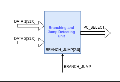
This unit is for detecting whether the branch or the jump has to be taken or not. Inputs to this unit are,
- DATA1[31:0]
- DATA2[31:0]
- BRANCH_JUMP[2:0] control signal (See BRANCH_JUMP for encoding)
Output of this unit is,
- PC_SELECT
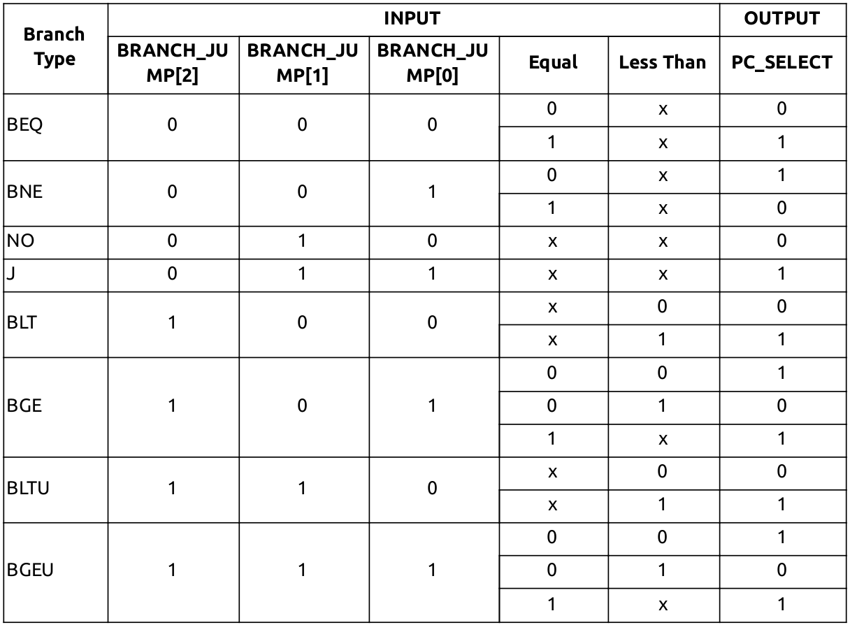
This unit will contain a comparator implemented using behavioural modeling and a combinational logic circuit to generate the PC_SELECT control signal. Branch and jump detection is done in 2 steps.
-
DATA1 and DATA2 values will be the inputs for the comparator. The comparator will output two 1 bit signals by comparing the input values,
- EQUAL - If DATA1 and DATA2 are equal this signal will be set. Else it will be cleared.
- LESS_THAN - If DATA1 is less than DATA2 this signal will be set. Else it will be cleared.
-
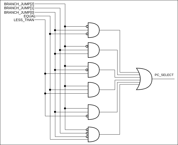
BRANCH_JUMP control signal, EQUAL and LESS_THAN intermediate signals will be the inputs to the combinational logic circuit. The combinational logic circuit will generate the PC_SELECT control signal depending on its inputs.
PC_SELECT Control Signal
PC_SELECT is a 1 bit control signal generated from the branch and jump detection unit. This signal will select the address source for the PC register. The PC register has 2 address sources.
- Address computed by the ALU
- Address computed by adding 4 to the current PC
| Address Source | PC_SELECT |
|---|---|
| PC + 4 | 0 |
| Computer address from ALU | 1 |